 Vintage Workshop
Services for Brough Superior motorcycles and their contemporaries
|
Vintage Workshop Services for Brough Superior motorcycles and their contemporaries |
A beginner's exercise in serious panel beating: Making a primary chain case for the Montgomery....
| From my previous scribblings, you may have understood that I had a
problem with the missing primary chain cover. Not only did I find it
difficult to decide what the primary chain cover should look like, I also
wanted to get it right!
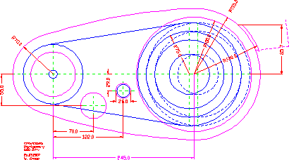
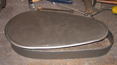
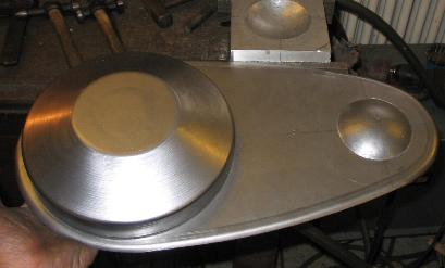
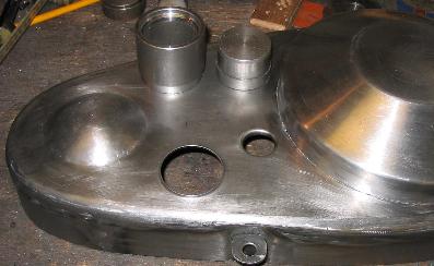
In the end I decided on the shape shown here. It owes something to the late 1920's / early 1930's Brough primary chain covers, but there are also a few Montgomery examples that legitimate its shape. And I find it looks good! So I decided to make it like this. I had a clutch dome that dear Geoff had made for me, but I decided it was too big. My sincere apologies, Geoff, but having this one as a backup gave me the courage to try and make my own. |
|
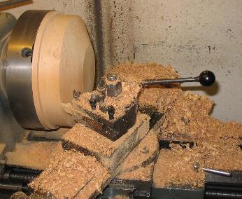
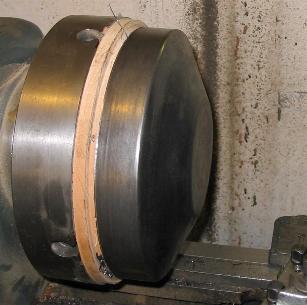
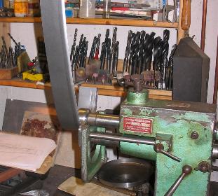
| So it was metal spinning time again. I was able to scrounge a piece of a
70mm thick plank of well dried pear wood which looked good enough. I cut a
230mm round bit out of this with a band saw. Then it went onto the faceplate
of my little Robling lathe.
A lot of sawdust (not really, but does turning wood produce swarf? chips?? or strands???) and I ended up with a nice mandrel to spin the clutch dome on. |
 |
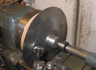
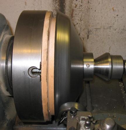
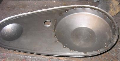
| Now, a big disk of 0.9mm steel plate, and COURAGE!
This does not look too bad, but buckles started springing up near the outer edge. Also, the lot would become unyielding, so I decided to anneal it. Easier said than done as such a big area radiates a lot of heat, and it is difficult to get it red hot with a propane torch! |
 |
| I annealed it two times and finished up with this. Not bad, not too nice either, but after trying it on I decided it was still too big. |
 |
| Thus some more sawdust and a new start. This time I had a bit more courage and shaped the bevel bit almost in one go. I was able to finish the whole thing without annealing, but found I had cut the disc a trifle too small, so the cylindrical bit ended up too short! |
 |
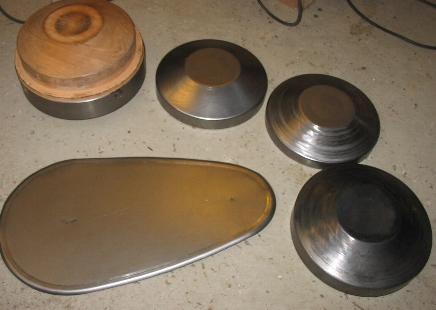
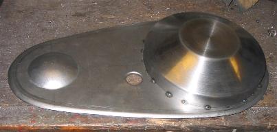
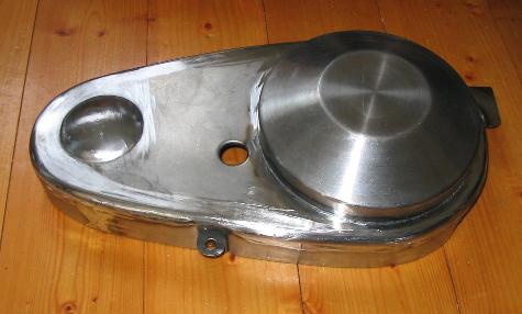
| The third attempt was quite successful, and took only about half an
hour. Not a bad learning curve, but total time was over 10 hours... You can also see the front plate here. It has already an 8mm radius beaded to the edge. That is another story: |
 |
| I wanted to join the cover and the sides in a nice big radius. I think
the best way to achieve this is by shaping half of the radius to each part
and the weld them up in the middle, where you can clean up the weld without
interfering with the flat surfaces.
To shape the edges nicely, a beading machine would be nice. After experimenting with some home-made rollers in the lathe and getting fed up with the lack of space around these I decided a proper beading machine (not sure if this is the right word in English!?).would be a good investment. I bought one on Ebay. The seller was an awful bummer, it took 4 weeks until I finally got the machine. It needed a strip, clean and rebuild with a bit of straightening here and there but was otherwise ok. It came with 14 rollers. However, not all of them were pairs, and I found none of them was useful for the job in hand. So I had to make some rollers first. I have never seen a pair of rollers shaped like this, but how else should they look if you want to bead a 45� radius to the edge of a part? There is precious little information about beading rollers on the internet - do you know a good page? |
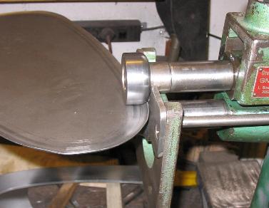 |
| Here I am rolling the radius to the sheet metal strip for the side of the case. The bending radius around the clutch dome and around the engine sprocket is determined by the angle in which you feed the strip in, so it took a while to develop the right "feel". |
 |
| So, this does not look too bad yet, I thought. |
 |
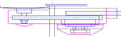
| Now, what to do next?
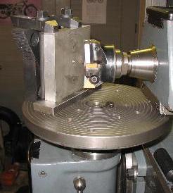
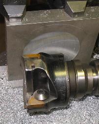
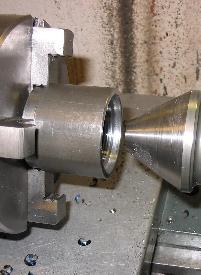
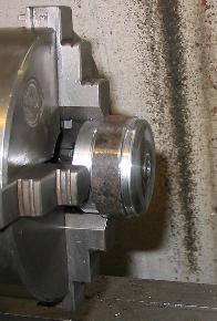
It is a bit hard to see on the drawing at the top of this page, but I wanted to have the small protrusion for the engine sprocket nut to be shaped spherical. And as I have some bad experience with welding distortion, I thought it would be better to beat this right into the plate, rather the welding a spun part in. Maybe a dab hand would beat out such a hump on a stump or on his shot-bag. For my level of skill I thought it would be better to make a die for it. A very clever way to produce a perfect spherical surface is the one shown to the right (no, I do not claim to have invented it!): As long as the diameter of the cutter is bigger than the diameter of the spherical surface, you will always produce a perfect sphere with this method; the radius of the sphere is just determined by the distance you set the plate from the centre of the faceplate. However, the spindle axis needs to intersect exactly with the turning axis of the faceplate, otherwise you will produce an ellipsoid - which looks interesting, but is not too useful for my purpose. |
 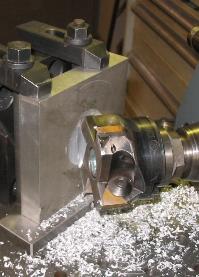 |
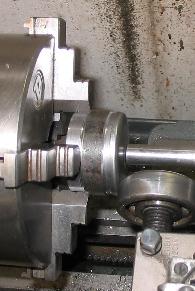
| All you have to do now is feed the machining spindle a little, then
rotate the dividing head for a quarter of a turn and measure if the diameter
of the spheroid is already big enough.
Now I had a die and a hammer. I wisely decided to practise first on a surplus bit of sheet. |
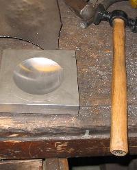 |
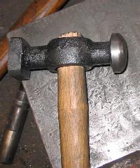
| The result wasn't too bad for a first attempt, but beat it how long I
would, the skin would still show some cellulite... Sitting down and having a think told me it was the fault of the hammer. I took the hammer head off, and changed the radius of it. Near the centre, I made the radius just a little smaller than the one of the sphere to be beaten, rounding it off towards the edge, to avoid nasty prints if the hammer should hit the surface at a slightly wrong angle. |
 |
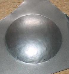
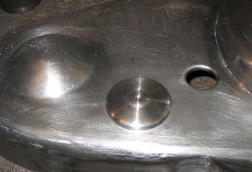
| The result was not 100% perfect, but I was happy enough with it. |
 |
| You see, I am a bit afraid of ruining the job in the welding. If it
cannot be avoided it would be better to ruin it as soon as possible, before
putting more labour in it, but anyway, after cutting the big hole for the
clutch dome I still had to try something else.
The chain case needs to have a hole where the footrest passes through it. A piece of 7/8" tubing going through a 1" hole with a sharp edge does not look too nice. So I decided the hole needed a beaded edge, too. |
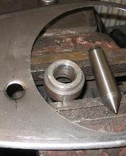 |
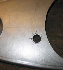
| I made a small tool, an aluminium ring with a about 26mm inner diameter
and a rounded inner edge, and punched the edge over with a special
footrest-hole-beading-tool (OK, abusing a nice Morse centre for such a task
is very near a mortal sin, but in fact it is an MT3 one, for which I don't
have any use on my machines, and it has a blunt tip anyway, so please bear
with me...) The end result looked quite nice. |
 |
| Now I could not push the dreaded welding off any more. ( Well, I could
still have made the chain inspection hole...) The problem is that I don't
have a TIG welder, just a MIG one. I can use a TIG at work, but I cannot sit
there for hours on end and adjust trifles.
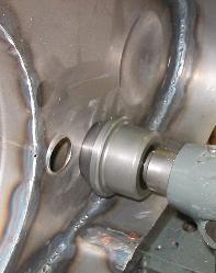
So the plan was to tack it all together with the MIG welder, and finish it with the TIG one later. I reasoned that I should start with the dome, as this would give the flat part some stability before joining it to the strip forming the side. I made the hole in the plate some 2mm smaller in diameter than the clutch dome, so I can more or less melt the edge down to make a joint. |
 |
| This worked basically quite well, although I still wonder if I will be
able to clean up the fillet nicely, once the thing has been welded all
through.
The next job was to make sure the outer edge was totally level. I spent an hour or two making small corrections here and there. |
 |
| Now it was about time to jump into the cold water - |
 |
| - and it did not work out too badly.
Anyway, with a TIG welder and a foot pedal current control this would have been a much more relaxed operation - giving it very short shots with the MIG under a rather high current is a risky and stressful thing! |
 |
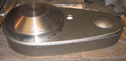
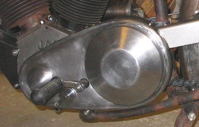
| Here I am just trying it on for size... |
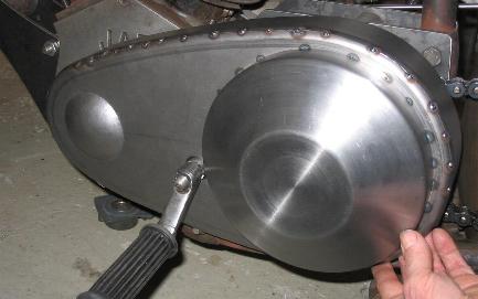 |
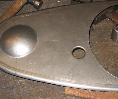
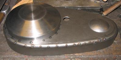
| Well, I have now found the courage to go ahead and weld it up. As expected, the weld around the sides went very well, but welding the clutch dome in gave some distortion to the flat surface. Fortunately nothing that could not be dressed out, so I am rather pleased with the end result. |
 |
| When I was about to fit the case to the bike, I noticed I had forgotten
to make the chain inspection hole.
This meant making another tool to shape a nice bead to it. Cutting a 42mm hole in the case was not too easy either - you don't want to use such a big drill on 0.8mm sheet steel, and it is to small to use a pair of (even curved) shears. I have a punching tool which does up to 30mm diameter, and the rest was taken out with a big countersink! I started the bead by pressing the edge of the bore into the radius tool with a 60 deg. centre on the lathe... |
 |
| ... and continued in the vice with a suitably turned mandrel. The result was nice... |
 |
| ... but this beaded hole wants a fittingly beaded lid!
So it was time to make another tool and a little spinning session. |
 |
| THAT IS IT!. Well, almost, I will have to make a clip for it as well... |
 |
| I used a piece of spring steel, softened it at the end where it clips
the cap, punched a little dimple into it, had some fun drilling a small hole
into the other (hard) end, made a little hex post with a stud for it and
there we were!
I once had a chain case made be master tinsmith Ernie Rowe. It was for my 680 Brough, and it took a while until it was delivered. I found it rather expensive but was absolutely delighted with the quality (you can see it on my 680 Brough pages). After the exercise described above I am thinking differently about both price and delivery time! And I will not compare quality.... :-( |
 |
If you have any comments please send an e-mail to
![]()
(sorry, this is not a clickable 'mailto:' hyperlink. If you want
to write me, please type my address in your mailer. )