 Vintage Workshop
Services for Brough Superior motorcycles and their contemporaries
|
Vintage Workshop Services for Brough Superior motorcycles and their contemporaries |
An oil tank for the Montgomery....
| The Montgomery's oil tank is a slightly tricky bit of sheet metal
fabrication.
It is soft soldered from relatively light gauge steel. It wraps, shaped like a horse-shoe, around the saddle tube of the frame, has a curved rear wall, side walls with a slight fold in the middle and a big cut-out to avoid the exhaust pipe of the rear cylinder. However, it does not have any 3-D surfaces that would require advanced metal-beating skills, just an endless number of beads to make up the soldering seams. I toyed with the idea of welding it up for simplicity, but decided to stay faithful to the original. It has a filler neck using the ENOTS type filler cap with the 3 expanding prongs, but in a smaller size. I was able to get such a cap (NOS) from Cornucopia enterprises, but I better don't tell you what I paid for it. Peter told me it he once had sacks of them, but now this one was the only one left...
|
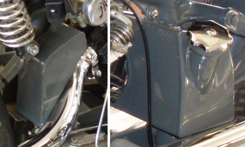 |
| Looking at the close distances to all neighbouring parts, guessing the shape and size from photographs will probably not do. I have thus asked fellow enthusiast Chris for help again. He could not be persuaded to lend me his tank, but took a lot of trouble making a number of rather clear pictures of it. Thanks a lot for that, Chris! |
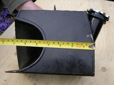 |
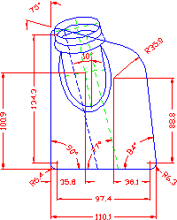
| This enabled me to make a drawing of it, and the pertinent development
drawings (sorry, not sure if this is the right word?).
In the extremely unlikely case that you should have a 680 ohv Montgomery Greyhound sans oil tank and need the complete drawing, please drop me a line!
|
 |
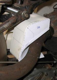
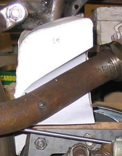
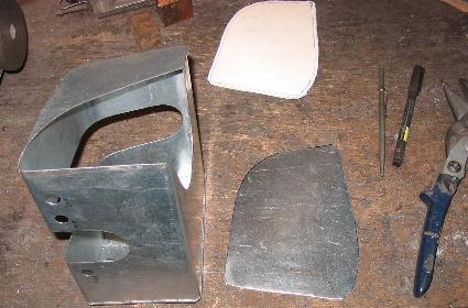
| Now I did not want to spend days in making a tank that would not fit.
Thus I made one from stout paper first, and tried it on. It fitted alright,
but I went through a number of changes in the exhaust pipe cut-out. Original
or not - I did not like to end up with a situation like the one on the NMM
machine.... This is version "1.e" on the bike, which illustrates that it took a while until I was happy with the fit of it... The main trouble was finding a shape for the exhaust pipe cut-out that gave reasonable clearance AND looked good, i.e. gave an upper edge running parallel to the pipe in the side view. I am aware it is debatable if you should depart from the original in the restoration of a historic vehicle, but it is apparent that Montgomery's went slightly wrong here, and the small correction will possibly save me some trouble in running the bike! |
 |
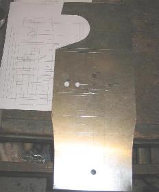
| So this shape went back into the drawing, and I could finally mark out
the main development on a sheet of metal.
Unfortunately I was not able to procure any tin-plated steel sheet, which would be the best material to use, as it solders very readily. So I will have to make do with zinc plated steel. This is giving better corrosion protection at least, which is wonderful - have you ever seen an oil tank rusting from inside?? :-) I managed to make the big cut-out for the exhaust pipe with a pair of shears without making a mess out of the surrounding sheet, but the tunnel for the saddle tube requires cutting two semi-circles with a radius of 22mm. I have a punching tool for 30mm holes which I used, but then I had to enlarge the holes to 44mm with a big countersink - a nasty operation! However, with a bit of filing the result was perfect. |
 |
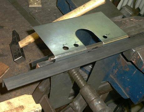
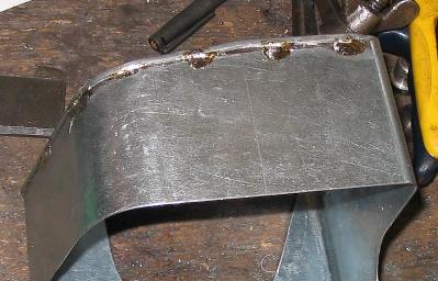
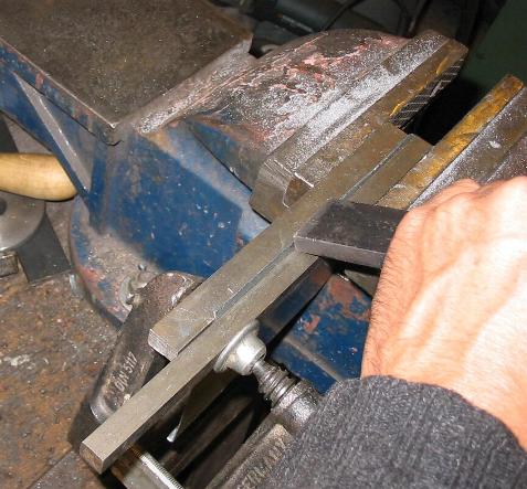
| Next I had to bend the whole lot. There are three 1/4" radii and one
1.5" radius to be made. The 1/4" is measured on the outside, so it is about
7/16" on the inside. You could try to clamp a bit of 7/16" bar into the vice
together with the sheet and a piece of angled iron, but then you can't see
very well what you are doing. So I decided to weld the bar to a piece of
flat steel 7/16" thick, see also picture above.
What you probably can't see on the picture: I scribed a line along the round bar exactly at the front. This proved very helpful in aligning the sheet. Bending was relatively straightforward then. The same cannot be said about the 1.5" radius. I did not afford a special tool in this case. Clamping a 3" tube and the sheet and an angle iron in the vice and bending the thing was an operation that required about 3 arms and a foot, so I was not able to take any pictures before the whole lot dropped out of the vice I am afraid.... |
 |
| The bend was alright, though, and I was happy to see the ends met up as
planned.
I had decided to make the joint within the top front radius. Making the necessary step with a pair of stepping tongs (not sure if you call them like this in English..) was not a problem, but bending the radius into the small end coming after the step was a bit tricky. |
 |
| I managed this as well, though I forgot to picture the setup. To make sure I will get a strong and oil-proof joint I prepared both areas to be joined by tinning them and then wiping the hot tin off, so I was left with what I would have liked to use in the first place - tin plated sheet. Here you see the prepared seam before and after soldering.
|
 |
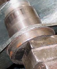
| Here you see the r.h.s. (exhaust side) panel after beading the edges and
pre-tinning. I will try to do a few pictures of the beading process when I do the r.h.s. panel. |
 |
| And here it is after tacking it on with a few solder spots only. I always do this, because I think it is as well to cross check any gaps etc. before running the whole joint. |
 |
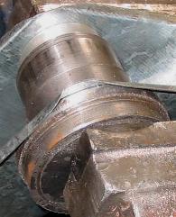
| After finishing the joint, you should see a nice solder penetration to the inner side. I agree it could be more regular... |
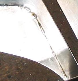 |
| .. but I am sure it is a good joint in spite of this. So far things are looking good, but another week-end is over! |
 |
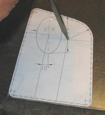
| OK, now for the left had side panel. With a bit more complex shape, I usually plot the drawing in scale 1:1, glue it on the sheet and punch trough the points needed with a scriber. |
 |
| I might have used the beading machine for doing the folding on the edges, but I found it is not really suited for small scale work like this. So it was back to the old iron bars and vice. |
 |
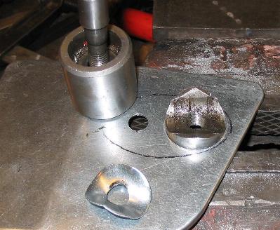
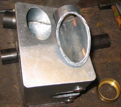
| Making the elliptical hole for the filler neck meant drilling, punching
and filing again.
Before beading the round bits, I tried the panel on. To my dismay, I had to find that it was about 1mm too small, so it would not slide all the way down the wedge-shaped side... #%!@!!! I'll have to start all over tomorrow. I wonder if I'll do the beading first, and the filler neck hole later on next time.... |
 |
| OK, a new start
This time I would do all the folding first, before attending to the filler neck hole. This is how I fold the round corners: I simply clamp the work to a suitable round piece of iron and hammer the edge over. |
 |
| This time the panel fitted well, so I'll make the elliptical hole again.
This is the punching device. A very handy thing, but I have only got inserts ranging from 15 to 30mm. A few bigger ones would be nice. |
 |
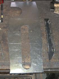
| Now it was time to attend to the two cut-outs. The one for the exhaust
pipe and the other one for the saddle tube. I made some paper templates to determine the shape of the cuttings needed. |
 |
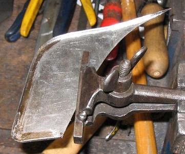
| The one for the exhaust has a rather strange shape. Bending the
non-constant radius seemed all easy in paper, but not so much in steel. The
fold on the left hand side was easy, but the ones at the rear corner of the
tank (upside right) took some time.
Here I am doing the fold where the "funnel" joins the front panel. I scribe a line where the fold wants to be, then I start folding with a pair of pliers. I don't do the whole angle at once, as this distorts the material too much and makes it very difficult to correct errors. Just about 30° for a start, then try it on. When the desired angle is reached, I hammer the bead flat on the edge of a suitable steel block |
 |
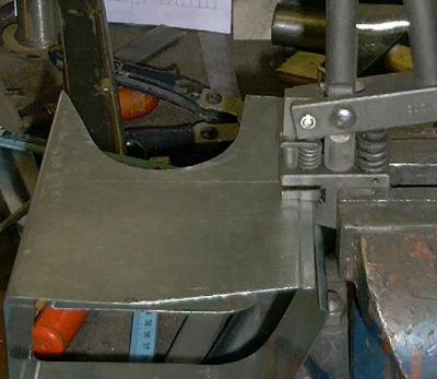
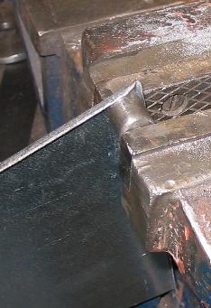
| This is how the thing looked after soldering it in place.
Not too bad, but it took quite a couple of hours until it really fitted.... |
 |
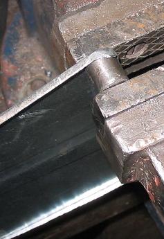
| The above picture has been taken a bit later on.
Indeed, after soldering up the exhaust cut-out bit, I realised that it was about time to attend to the stuff that goes into the bottom, i.e. the two threaded insert for the fastening bolts and the one for the oil tap. Having my share of experience with leaking tank studs in soft soldered Brough tanks I decided to play safe and provide all these inserts with a second flange which will be soldered to the inside of the tank. The oil tap thread is very near the exhaust cut-out, so that was a bit awkward to solder - at least it would have been easier had I done it before closing the side! |
 |
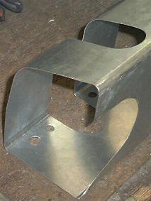
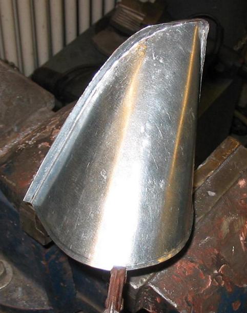
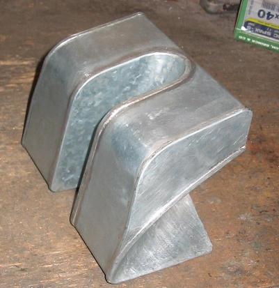
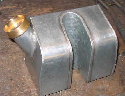
| The piece around the saddle tube was relatively straightforward now. Just a single 180 degree bend around a suitable piece of tubing, a number of straight folds... |
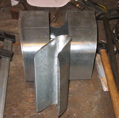 |
| ... and a number of corners.
While making this tank I was really rewarded for keeping a big assortment of round iron bits! You know, they might once come in handy...and they did! |
 |
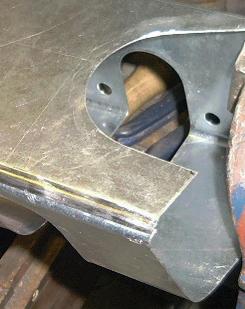
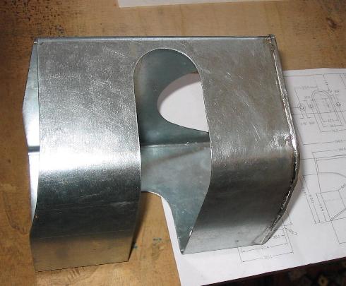
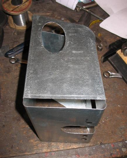
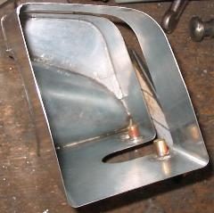
| So far things are looking good... |
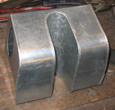 |
| ...but if you look into the tank, you wonder how someone could have designed a thing like this, and, how much oil will it hold! | 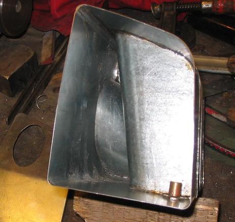 |
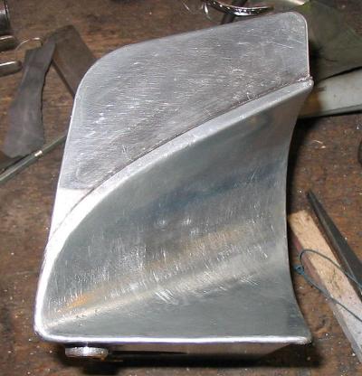
| So far it looks quite good, I find... |
 |
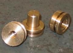
| ... but it still lacks a filler neck!
Unfortunately I had mislaid my camera while making these bits, but maybe there is some good in it... the whole page is much too long already anyway! I made the tube from a strangely sinusoidal cut of sheet metal (the shape of which I determined using a paper pattern), and closed it with a little stepped overlap. Bending the flange took some patience but wasn't too bad. The neck top I turned from brass, with a little peg to give the 3 prongs of the lid a grip silver soldered in |
 |
| So, that's it! Well almost; I have not soldered the side panel yet as I still need to decide on the top attachment bracket. |
 |
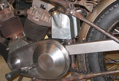
| Another weekend, but I had hardly any time to spend in the workshop.
Well, at least I made the two bottom brackets on which the tank sits.
This is how it looks on the bike. |
 |
| to be continued... |
If you have any comments please send an e-mail to
![]()
(sorry, this is not a clickable 'mailto:' hyperlink. If you want
to write me, please type my address in your mailer. )