 Vintage Workshop
Services for Brough Superior motorcycles and their contemporaries
|
Vintage Workshop Services for Brough Superior motorcycles and their contemporaries |
All those little bits...making a set of footrests and a brake lever
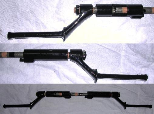
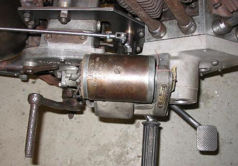
| Most thankfully, the de Pater family from Holland had sent me these
pictures showing the footrest assembly of their Montgomery bike. They show
clearly what the original setup looked like. I took a look at the
contemporaries of the Montgomery, hoping to find some Ariel, BSA, Rudge or
whatever footrests that are at least similar but, alas, I couldn't spot a
bike that used this system of serrations for adjustability, nor the single
pin securing the tube at the engine plate end. So I decided to make the footrests from scratch. (Now, please don't tell me the footrests of the ubiquitous Bezzumph would have fitted right away...) |
|
| In German engineering terms, this type of flat serration is called
Hirth-Verzahnung. Manufactured with high precision, it is an admirably
clever way of accurately joining two shafts with high repeatability. It was,
for instance, used to join the crankshaft halves of the twin cylinder Adler
engines in the middle. This allowed the two crankshaft sections to be
installed on either side of the central crankcase wall and to be
connected within the central bearing by drawing them together with a central
differential thread bolt. By the way, can anybody tell me how is this
accomplished in Scott engines? Well, we are only dealing with footrests here, thus no exotic precision is called for. Anyway, to correctly manufacture this type of serration you need to know what you are doing. If you mill the serrations with a prismatic cutter, you need to incline the axis of your dividing head by exactly the right angle. This angle depends on the tip angle of the cuter and the number of teeth. The trick is to make the tooth pattern symmetrical to the central plane; only then two identical parts will fit to each other. I had to do a little geometrical study to derive this angle. I am afraid I have only noted it in German, but if you are interested, here it is. Alpha is the tilt angle of the dividing head, and t_z is the feed depth. |
|
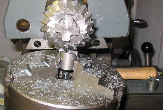
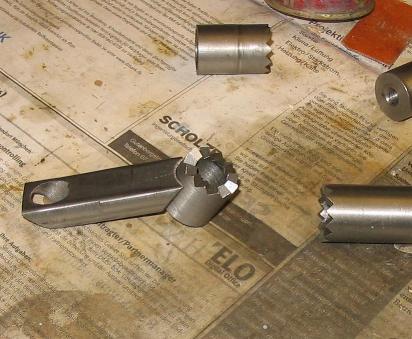
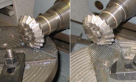
| Here is the practical application of the theory.
In the lower right corner you can see a finished bit. |
|
| Of course a few other bits had to be fabricated, until I could eventually weld them all up, followed by an amount of filing and grinding until they would look like the original castings. |
|
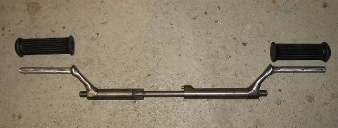
| Which I hope I have achieved reasonably well.
Please bear with me, I did not mill the windows into the tubes, which on the original parts served to hold the sand cores during the pouring of the castings. In practical use, they only allow all the dirt and water to go in and give you a hard time in dismantling the whole lot, so I think I can do without them. |
|
| Another slightly time-consuming exercise was done on the brake lever. I wanted a nice foot pad with the original criss-cross pattern. I don't think a material with such a surface is available from the shelf, so it was milling time again. |
|
| You might shake your head over someone spending two or three hours to
make knurled pad measuring 1.5" by 1.75", but I think it was worth while. I spent another day making up the whole lever, pivot and bushes etc, and I think the whole setup looks quite ok now. |
|
If you have any comments please send an e-mail to
![]()
(sorry, this is not a clickable 'mailto:' hyperlink. If you want
to write me, please type my address in your mailer. )