 Vintage Workshop
Services for Brough Superior motorcycles and their contemporaries
|
Vintage Workshop Services for Brough Superior motorcycles and their contemporaries |
MAGNETO REWINDING: last update 10/2003
I had given the story of my coil winding machine earlier. I had bought it because it was cheap and because I was curious if I could not make a better job of rewinding a magneto armature than certain specialists I had tried before.
But I can tell you, this is not an easy one....
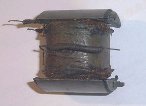
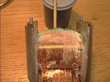
| This is how an old armature coil usually looks. Normally the shellac insulation has gone soft and it will not give a good spark any longer. |
|
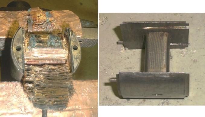
| The fine secondary winding is best taken down using a sharp chisel, as
you will not be able to count the turns anyway. What you find is a great number of layers wound with a very fine (0.07mm dia.) wire, separated from each other with very fine insulation paper. Below this, you will find 4-5 layers of thicker wire (0.7 ... 0.85mm) which make up the primary winding. These are separated from each other by a thin shellac impregnated cotton insulation; the primary winding has between 160 and 180 turns. |
|
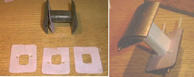
| You need to strip all of this off (making notes of what you found!), clean the armature core, make 4 cuttings from insulation material for the sides and wrap the centre core with fleece insulation. And of course, put some insulation tubing in for the start and end of the primary winding. |
|
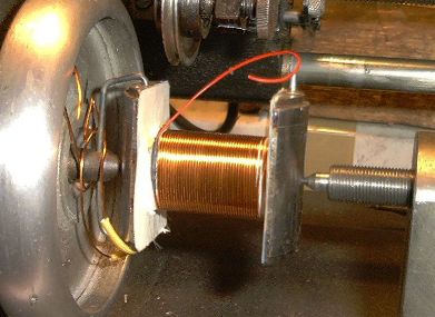
| Now, you can start winding.
I use a thin silk cloth for separating the layers of the primary winding. Not so much for insulation, but for mechanical separation, to avoid chafing of the lacquer insulating the wire. Mind you, the whole thing will be vacuum-impregnated later on. |
|
| To make the transition to the secondary winding I use a bit of very thin multi-strand wire. |
|
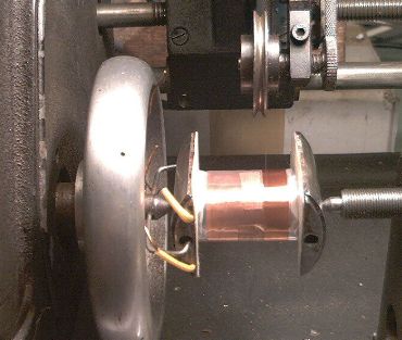
| Now, the secondary winding has to be done. You have to get the feed rate
just right (and the tension, of course...) to avoid any crossing of the
wires. Each layer has to lay perfectly flat and is topped with a 0.025mm
thick polyester insulating sheet.
Note you do not wind the secondary winding over the whole width of the core. |
|
| The farther you get on, the narrower you have to make the layers. There
are two reasons for this:
Firstly, you do not want to have the now very high voltage too near the iron core and secondly you do not want sparks around the edge of the insulating paper. When you have done about 11000 turns and have not broken the wire nor made any loose turns which will slip out to the edge of the insulating paper you only have to deal with the HT terminal end. For the transition to the 0.9mm terminal wire I use a piece of fine multi-strand again as it is very easy to break the thin wire in manipulating the thick one that is needed for the terminal. |
|
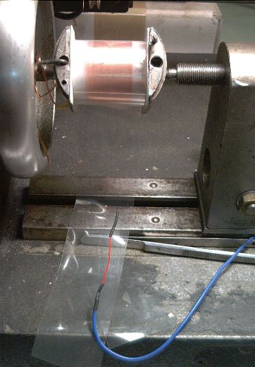
| Now, the whole thing is topped off with a few layers of heat-shrinking polyester fabric ribbon. |
|
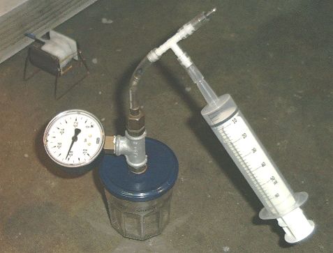
| Next step is vacuum-impregnating the whole coil. It took me a while to
find out how to do this without buying a very expensive machine.
My device now consists of a marmalade jar, a big disposable syringe and two pushbike tyre valves, and I can get down to at least 95% vacuum with this one! You will have to apply vacuum and atmospheric pressure two or three times one after the other until all the empty spaces are filled. |
You can either use a special thermosetting Polyester resin obtainable from rebuilders of electric motors, but this requires a special oven to set at some 110°C. Don't try to do that in the kitchen stove (at least if you are married and want to stay so) as the fumes are not only unpleasant but probably poisonous as well! Or you use a low viscosity two-pack Epoxy resin. This does not stink and you can cure it at some 50°C in front of an electric heater. |
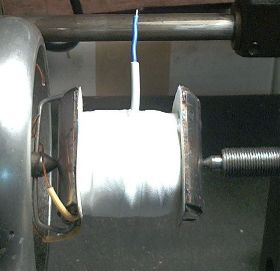
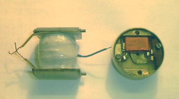
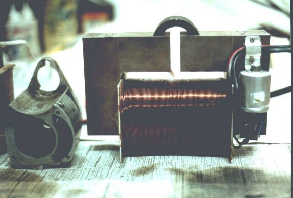
| Now, this is the finished coil.
The rear end of the armature has been treated to a modern condenser. You will need an impulse-proof type, and the problem is that most of these are not flat enough to be accommodated in the restricted space. |
|
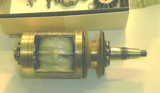
| Now, here we have the finished armature.
A word of WARNING: Unless you enjoy a real challenge, never try to build an armature from bits that did not belong together originally. And, before dismantling, put some centre dots on adjacent parts to make sure how the bits were fitted. I once trued up an armature made up from odd bits, it took me more than half a day! |
|
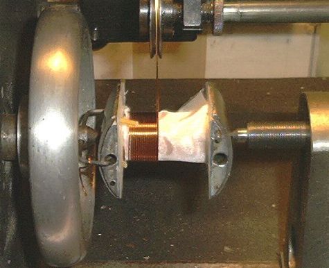
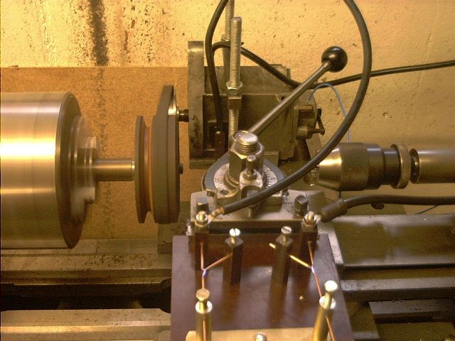
| Now, this is the proof of the pudding!
I found there is no better way to test the armature than running it for a few hours on a test rig. I made a belt drive and an attachment to put it on my lathe, which has variable speed drive anyway. To deal with V-twins you need two test spark gaps. I run my mags for 3 hours at some 1500 rpm with a 1/4" spark gap. If you go back to say 200 rpm then and you still get nice reliable sparks you should be alright and ready for the road. |
|
| But it has been a long way... The first armature I had rewound sparked quite nicely, but only for a minute. Then it would arc internally across the windings. I had used silk insulation throughout, and had tried to do without vacuum impregnation, brushing polyester resin on every layer as I wound it. The post mortem did not look too spectacular, but I found the layers were too wide as well. |
|
| The whole thing took me some weeks of experimentation, but the third
rewind finally worked quite alright. You might wonder why I am giving the fruits of all this labour away for free, but there is a simple reason: |
I will never do this for a business.
Winding the fine secondary coil with thousands of turns of hair-thin wire is no good fun, it is such a strain on the eyes, and unless you are really professionally equipped it will take very much time. I reckon I can do a complete armature overhaul now in one day if nothing goes wrong. But there are people out there doing this for less than 100 Pounds. THE CONCLUSION IS: IF YOU KNOW SOMEBODY WHO IS DEFINITELY DOING A GOOD JOB, PAY THE MAN!! But ask around until you find a number of people who have done a few thousand miles on a rebuilt magneto. And ask for a warranty. I think a very good company in Southern Germany is "Bayerische Magnetzuender". Have a look at their homepage on http://www.magnetos.de/ They are taking a very thorough and scientific approach to the whole thing, and really seem to know their stuff! 11.11.2024: I recently got across the homepage of "The Magneto Guys", https://www.themagnetoguys.co.uk/. I think that is a page worth looking at! I have no personal experience with them, but these guys really seem to know their stuff, and, from the way they present their workshop, I feel they LOVE to do what they are doing. If you live in England and have a magneto in need of some TLC - why not give them a try? |
| Ah, I forgot one thing:
You might have to do something about the magnetism. On the earlier magnetos you can take out the magnet to re-magnetise it. But you will need a very strong magnetic field. Big iron cross-sections and a heavy coil with about 30000 Ampere-turns. And I found you have to slide the magnet from the coil onto an iron keeper, and from that into the case, otherwise you lose too much magnetism. |
To judge the magnetism make the following test: Assemble
the magneto without the contact breaker (and without a dynamo on it, of
course.) It should now spin quite easily. Now put the contact breaker on,
but NO CAM RING. Now the primary winding is short circuited. If you turn the
bare shaft slowly with two fingers now, it should stop at the point where
the polarity reverses, requiring a substantial effort to turn it over this
point. |
Any kind of feedback to
![]() is
appreciated
is
appreciated
(sorry, this is not a clickable 'mailto:' hyperlink. If you want
to write me, please type my address in your mailer. )