Vintage Workshop
Services for Brough Superior motorcycles and their contemporaries
|
Vintage Workshop Services for Brough Superior motorcycles and their contemporaries |
Sturmey Archer gearbox page last update: 10/2022
|
After looking at all the bits I have accumulated over the years I came to the following conclusions:
- Grease'n oil lubrication is the accepted compromise to keep some lubricant inside the gearbox, but it is not really a good thing.
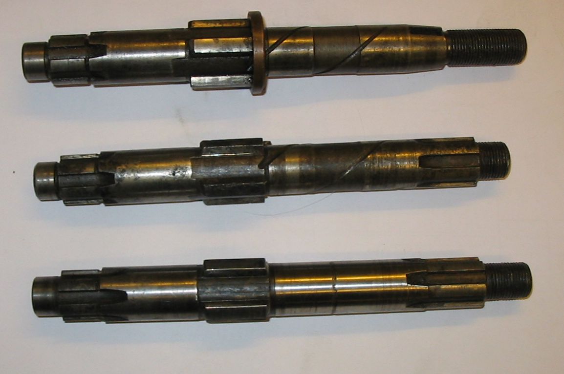
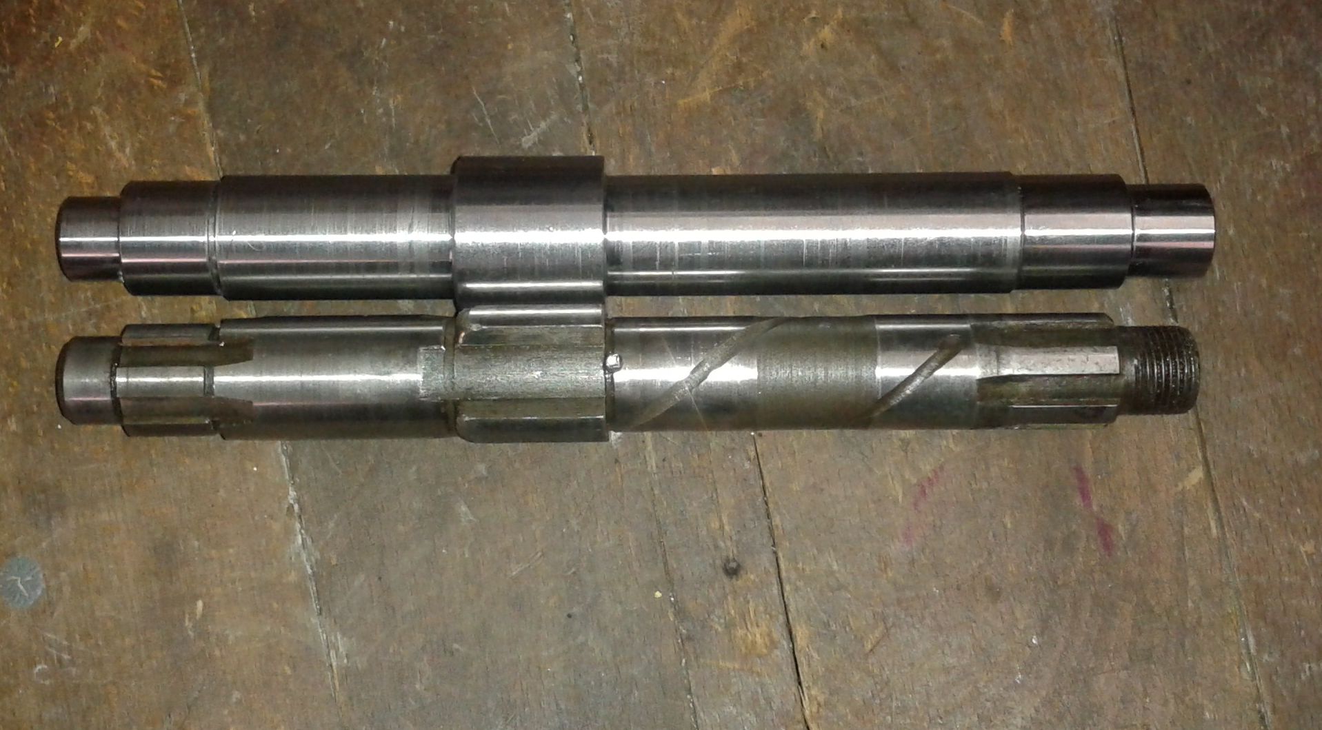
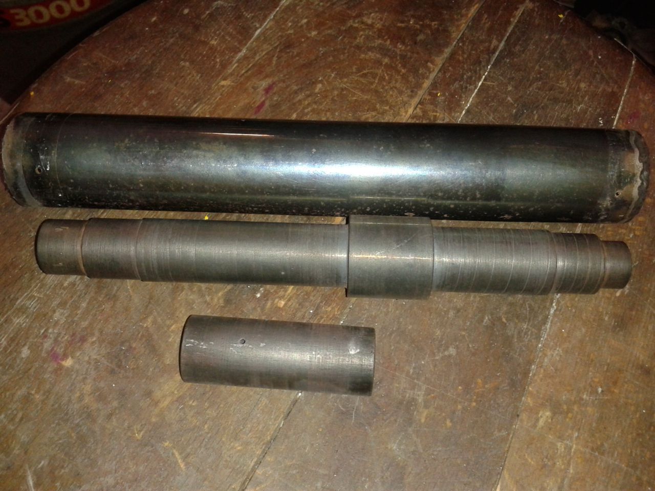
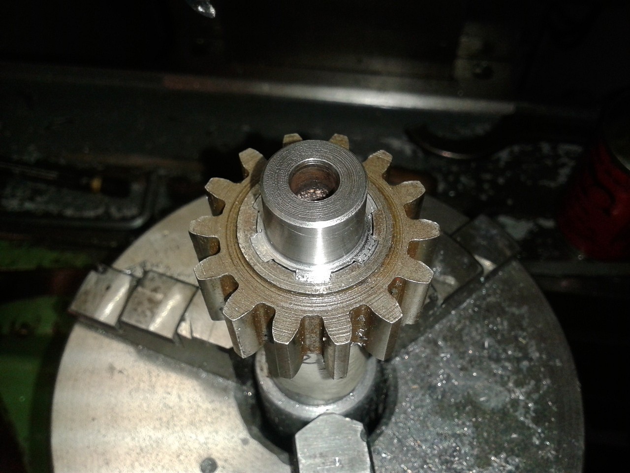
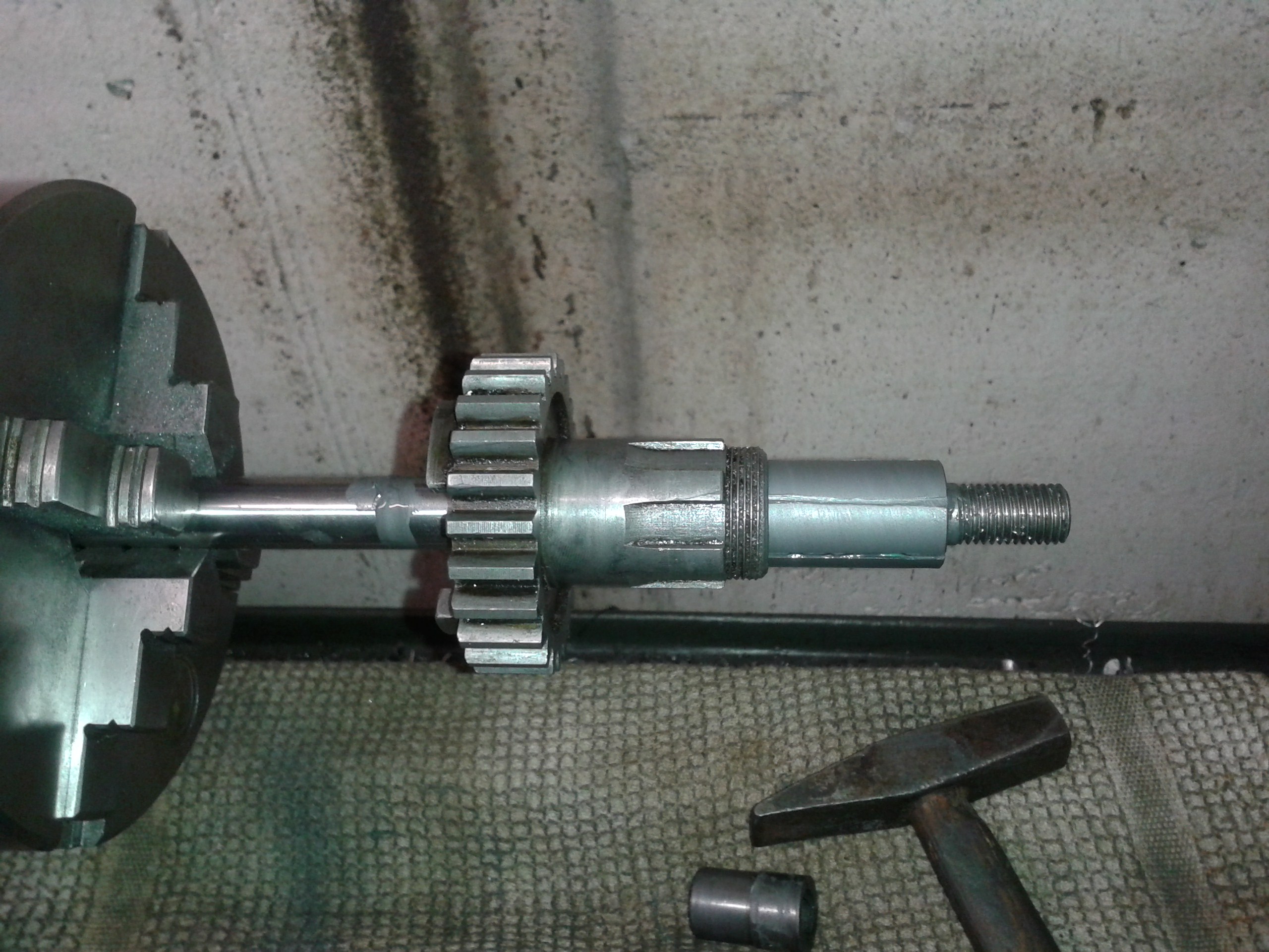
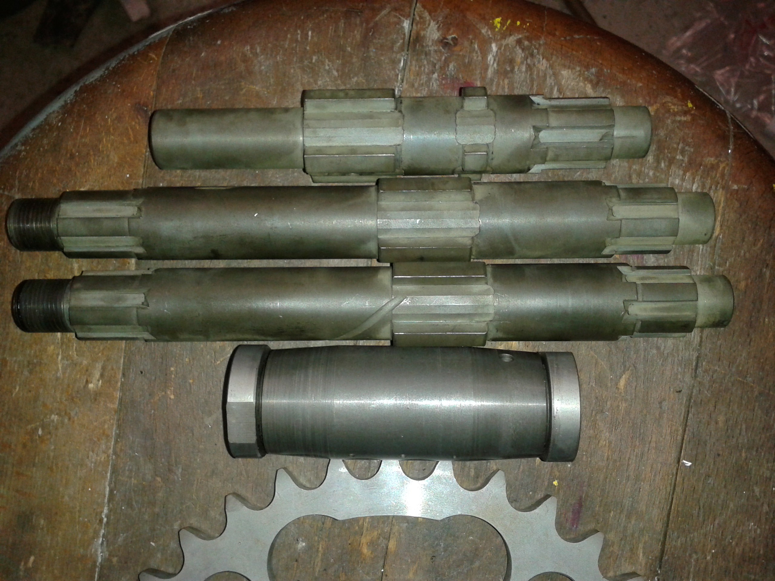
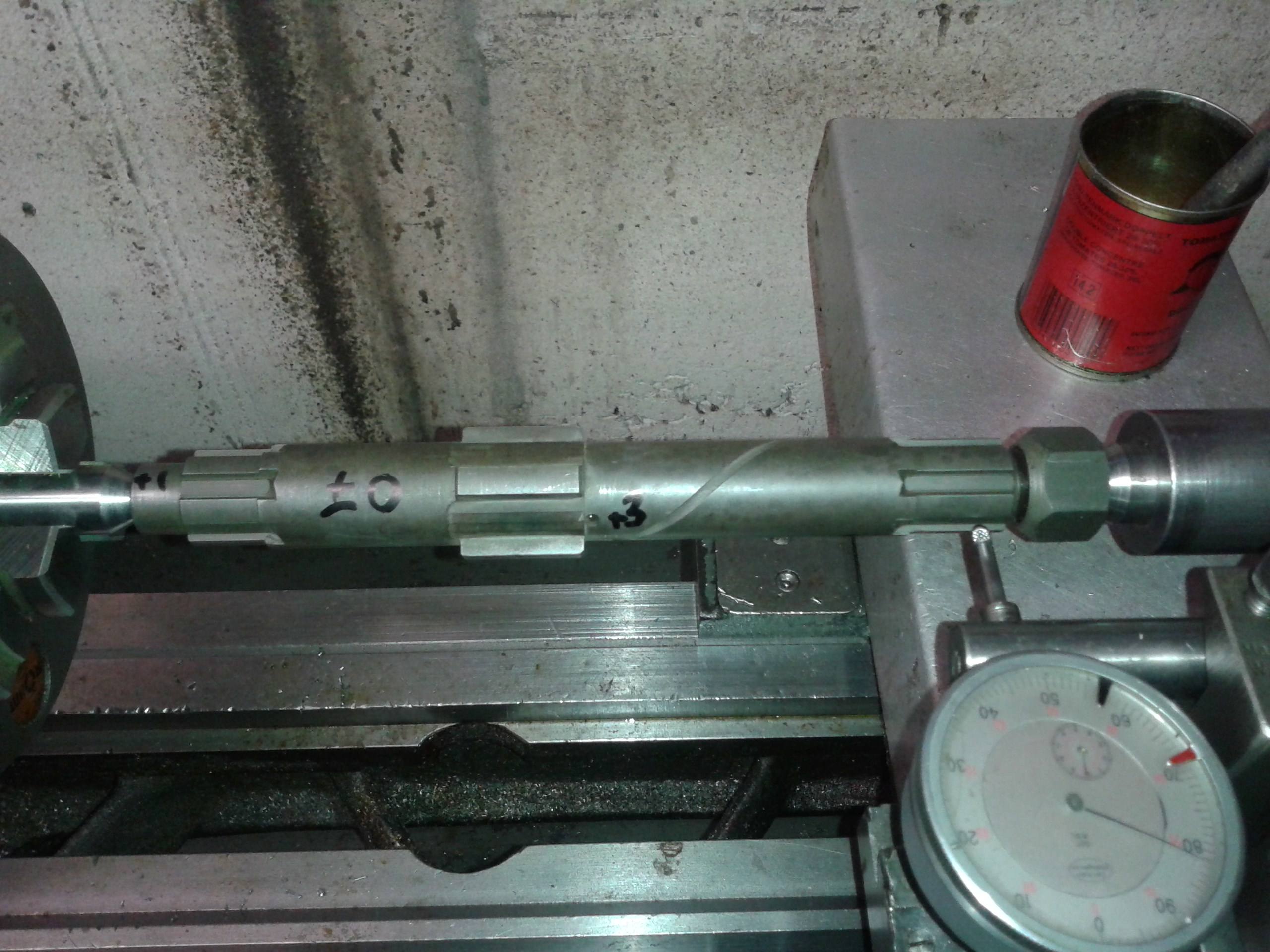
Have a look at these three main shafts: All of them have scoring marks from running inadequately lubricated in the sleeve gear.
Measuring them up showed me that they were significantly worn, especially at the outer end. |
|
|
I made some enquiries about hard chroming or metal spraying the portion of the shaft that goes through the sleeve gear, but gave that up because of the worn splines and some other issues. |
|
|
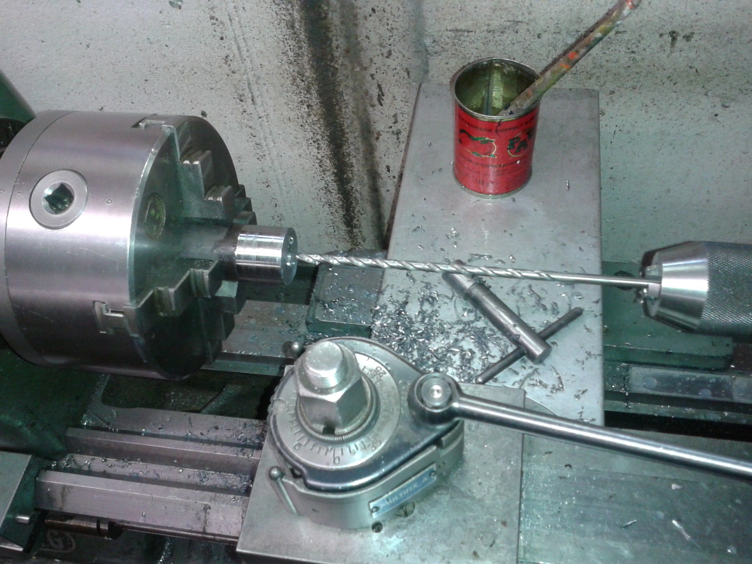
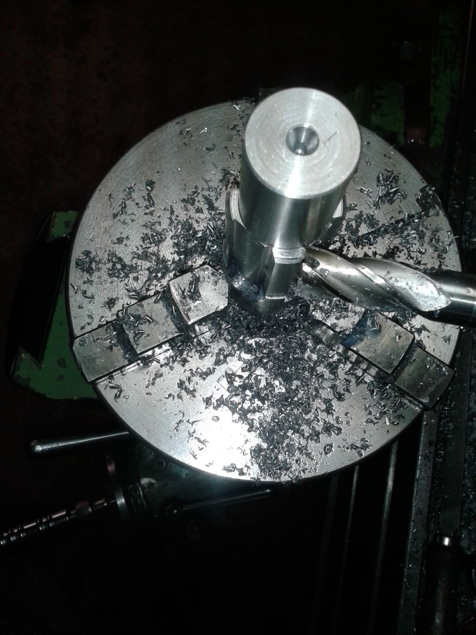
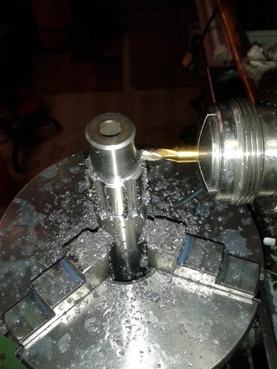
So I obtained a metre of 18CrNiMo7-6 case hardening steel and set to work. First job was to drill the bore for the clutch actuating rod. You need to drill from two sides, but only after VERY carefully centre boring the respective end. If you start drilling only slightly out of centre, your drill will be way out when it meets the bore from the other end. And you need to drill quite gently, removing the drill every few millimetres to clear the swarf - you don't want a broken drill stuck in your piece of work... Actually, this is why I did this tedious job up front, so only a piece of material would be lost in case... |
|
|
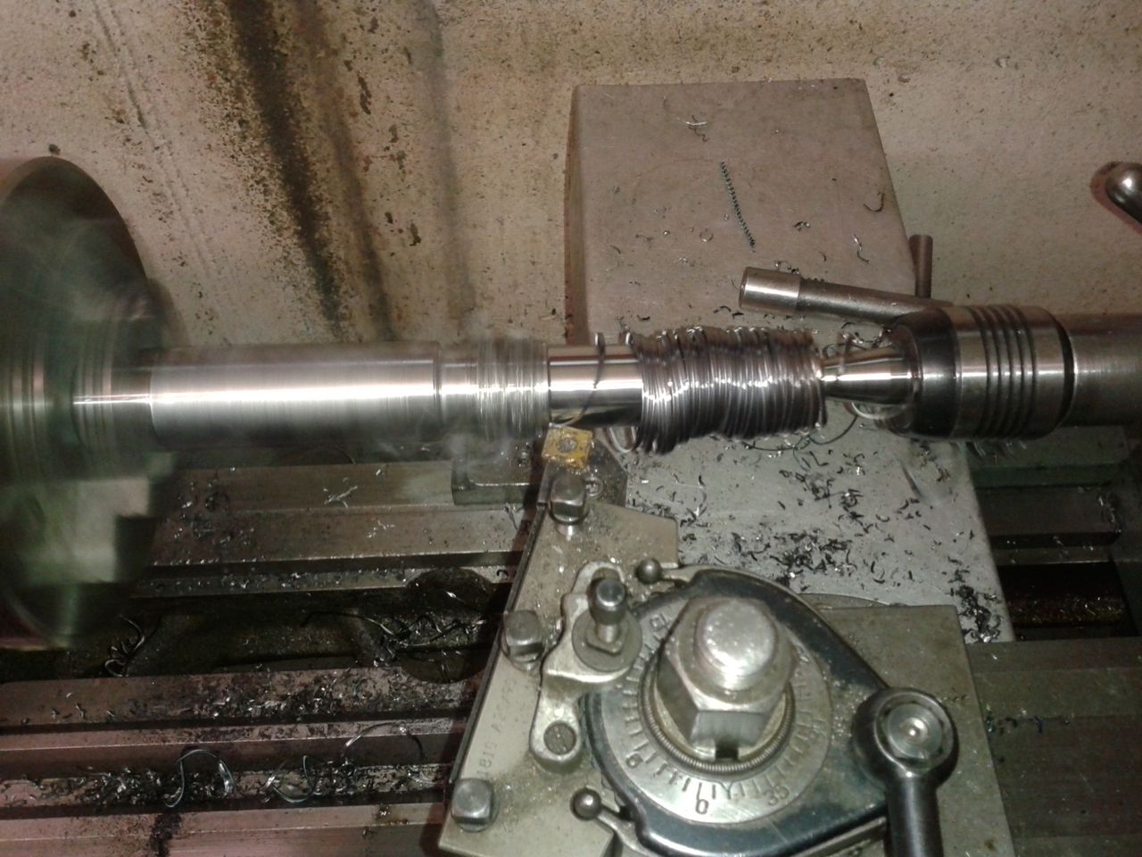
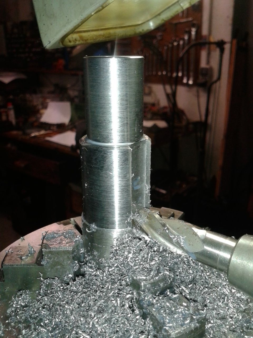
Rough turning the job was nothing special, save for the fact that the material produced long hot and sharp swarf which - in the best case as seen here - wrapped up around the work. Sometimes it would curl up and point in my direction... |
|
|
This is how it looked then. |
|
|
I then encased the bit in a sand-filled piece of steel tube and annealed for two hours it in my wife's pottery kiln at 600° to relieve any potential stress in the material in the hope of thus minimising the distortion in the hardening process. |
|
|
A measuring session before and after showed no measurable difference, so I could have saved this effort...
|
|
|
Before having a go at milling the various splines I tried things out on a dummy piece. |
|
|
... and here I am cutting their sides. |
|
|
Now I could round out the base circle between the splines in a series of cuts... |
|
|
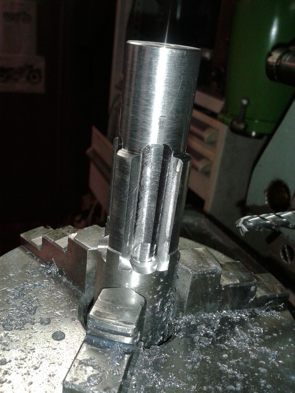
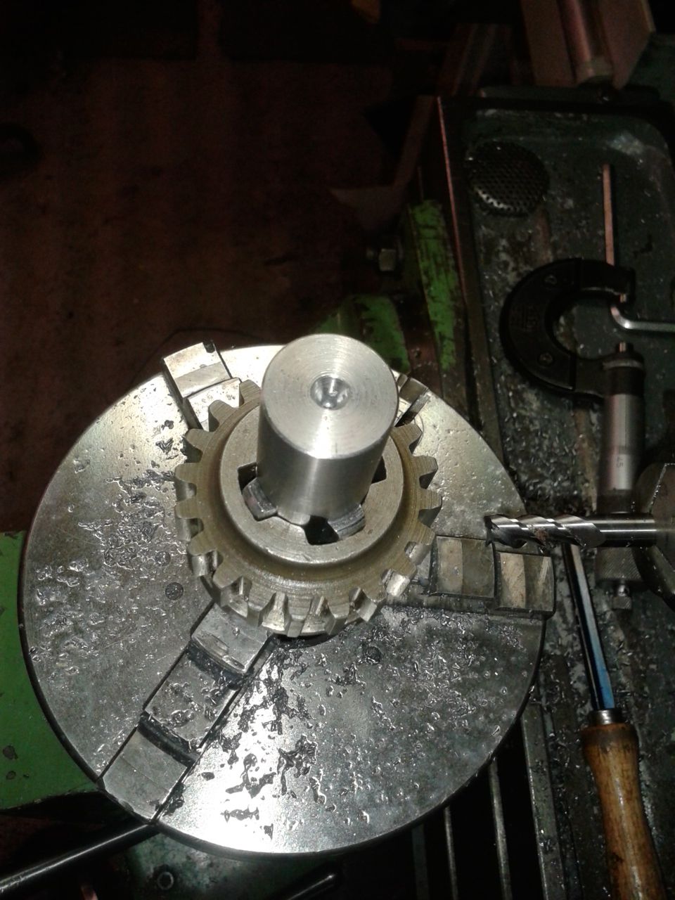
... after which the gear slid nicely on. |
|
|
Similar procedure in cutting the splines for the fixed gears... |
|
|
Only difference here is that you want the width of the splines correct to less than 1 thou, especially for the clutch. You'd really want to have a nice snug sliding fit without any shake! |
|
|
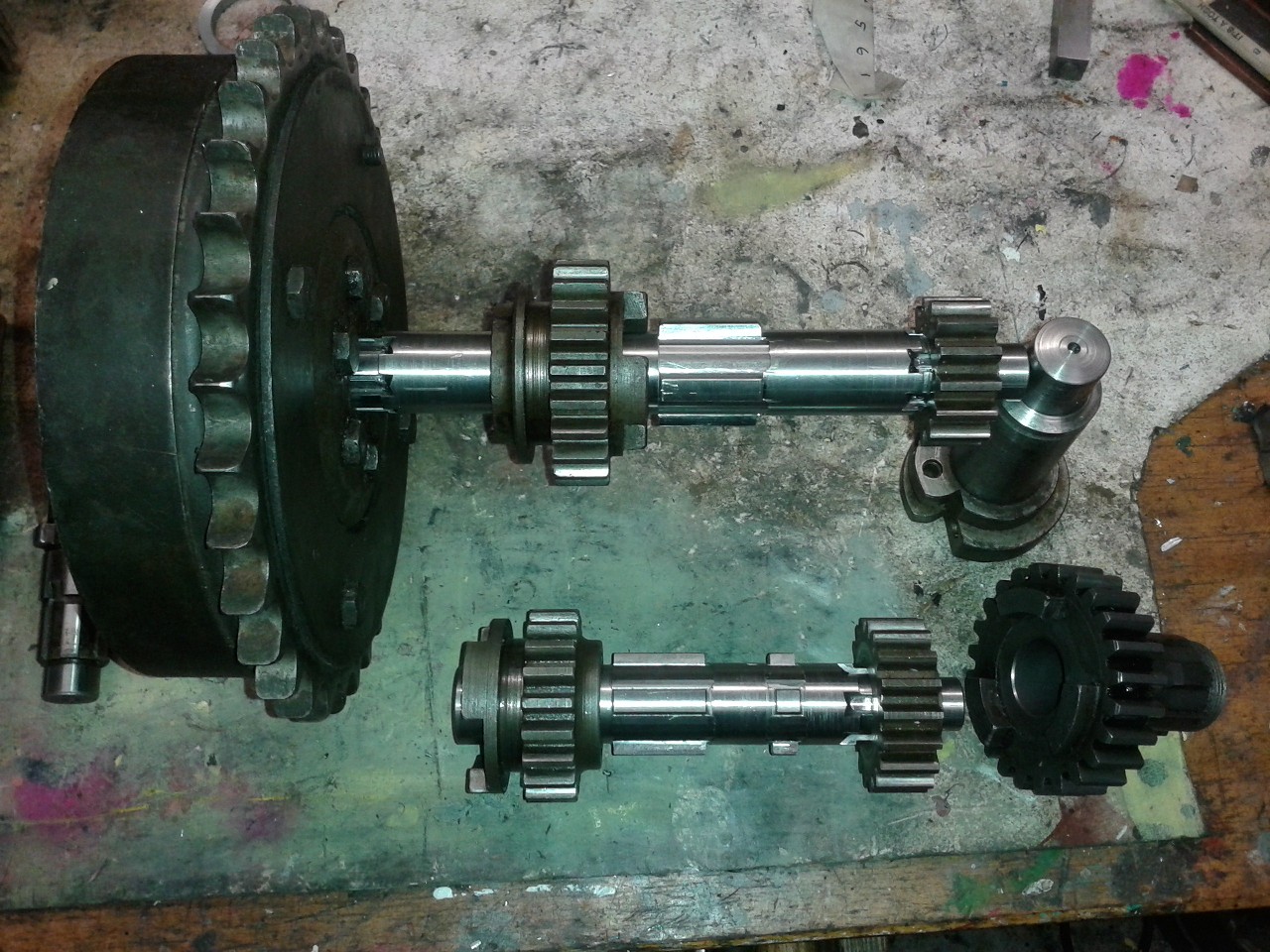
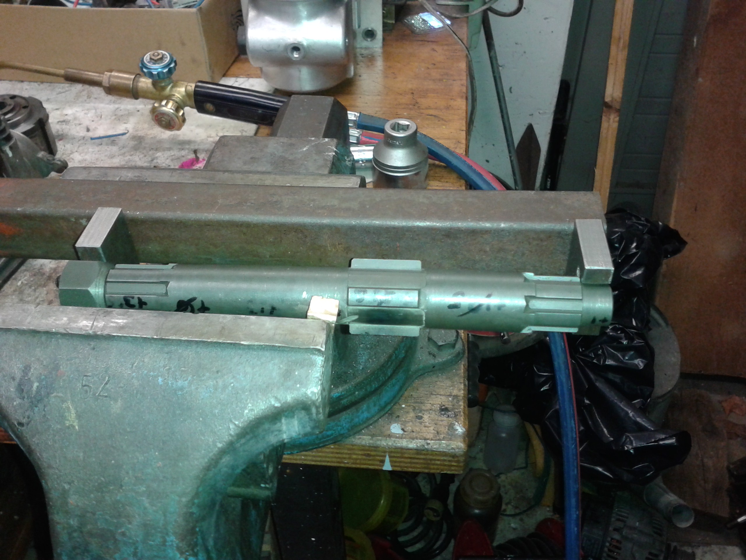
I made a new layshaft as well, especially because the sliding gear and the kickstart gear were a pretty loose fit even on a NOS layshaft I had. Without boring you with any further small steps - here are the two shafts almost finished. |
|
|
As mentioned before, I found all the gears having rather large running clearances on their respective part of the shafts - typically some 10 thou.
I don't know if this is due to the wear and tear of the decades or if it was like this from new.
If the latter, it is probably due to the fact that you could buy spares that needed to fit, taking all the manufacturing tolerances over the years into account.
Or did Messrs Sturmey and Archer consider these large clearances necessary for the grease lubrocation of those days?
Be that how it may, if precisely manufactured and running in oil, one thou should be just right. |
|
|
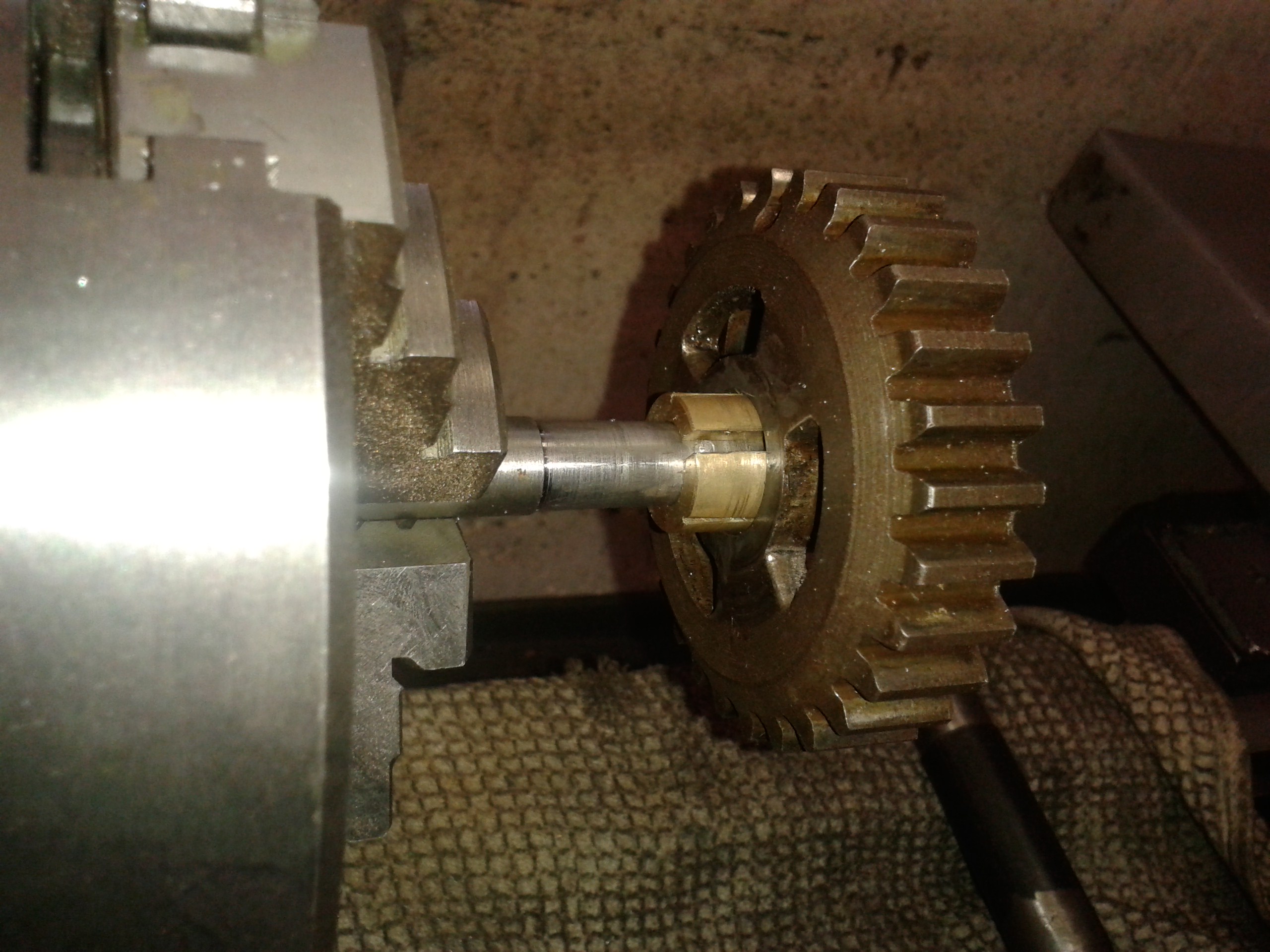
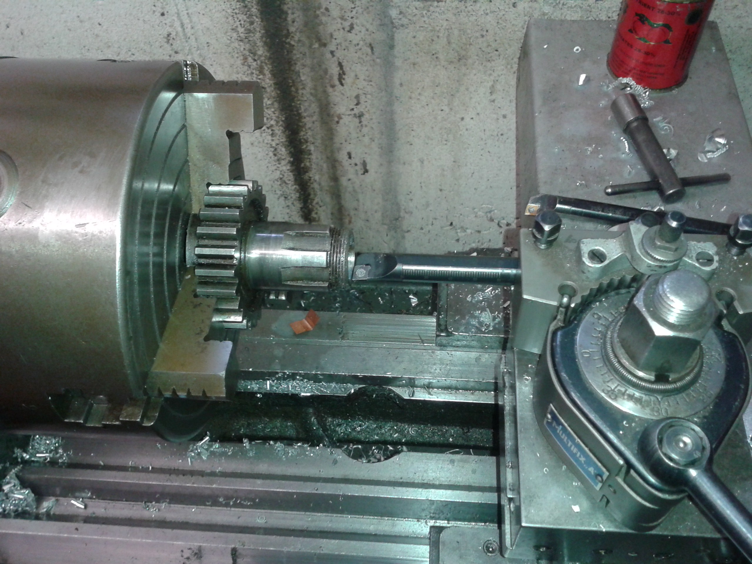
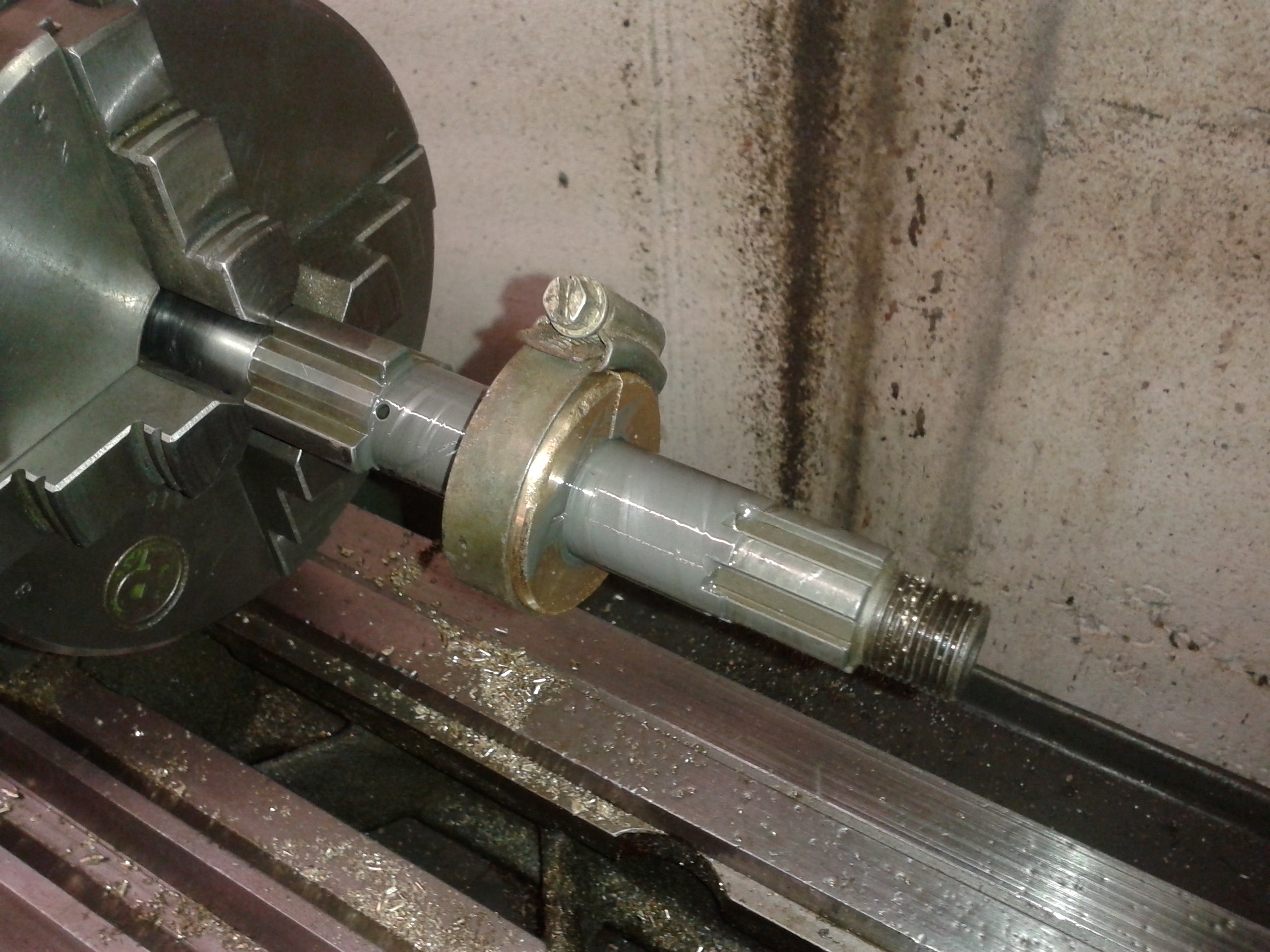
While the shafts were away for case hardening I cleaned up the parts running on them. Here I clean up the bore in the sleeve gear. CBN inserts make a wonderful job of machining hardened steel these days, but they do not tolerate mistakes easily... |
|
|
Still it is as well to make up a lap and lap the bore if you want it to be quite smooth. |
|
|
Likewise I treated the bearing surfaces of the sliding gears, but it seems I have lost the pictures I have taken...
|
|
|
All seemed well, but, unavoidably, the shafts had distorted a little during the heat treatment. |
|
|
I made a jig to to apply some brute force and tried to straighten the shafts cold.
However, even bending the shafts by as much as 2.5 mm did not result in any permanent deformation -
the shaft would just spring back into its original shape.
|
|
|
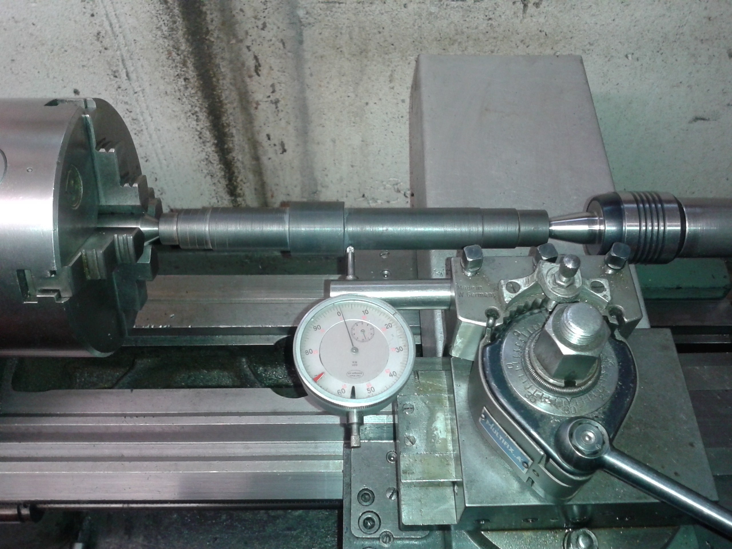
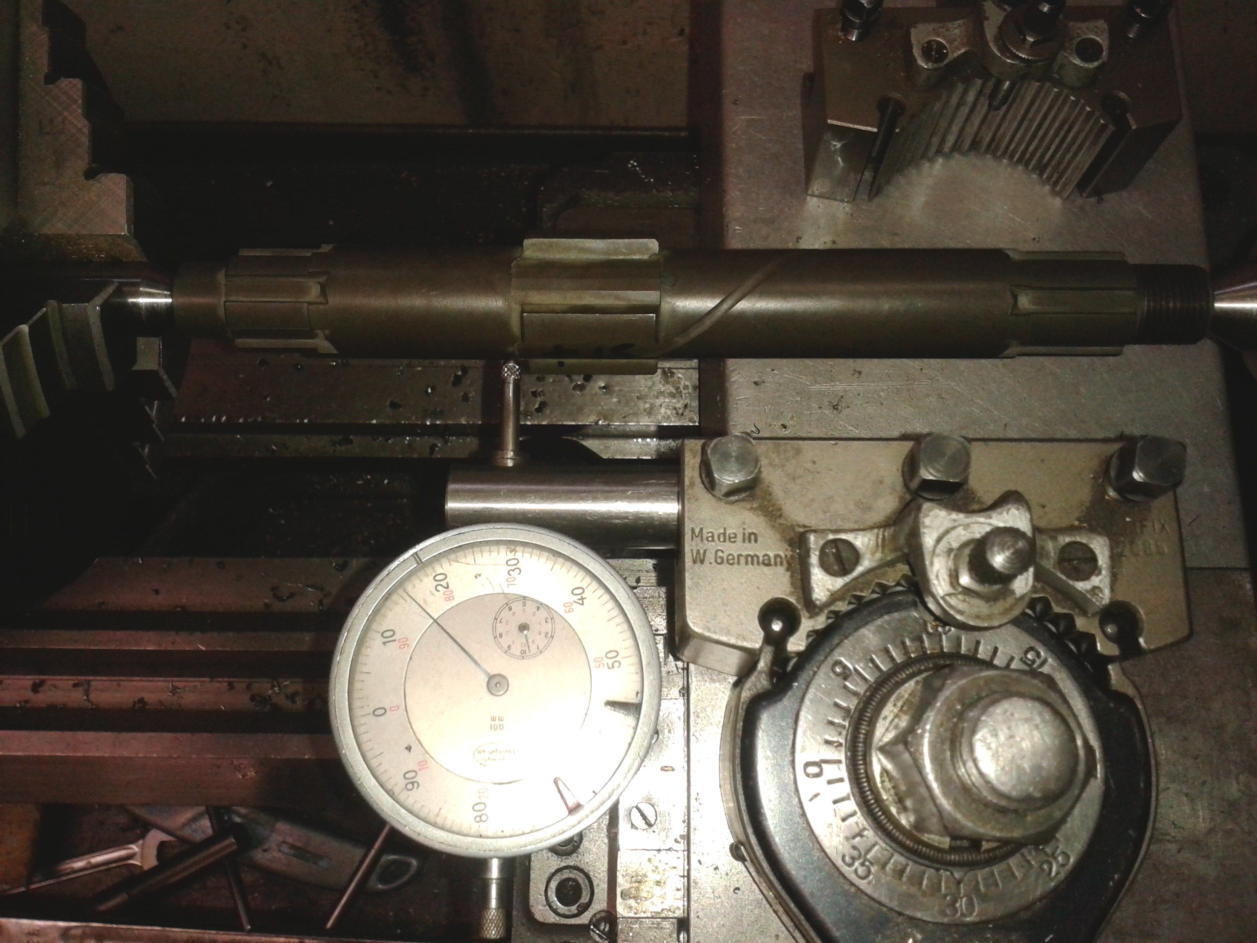
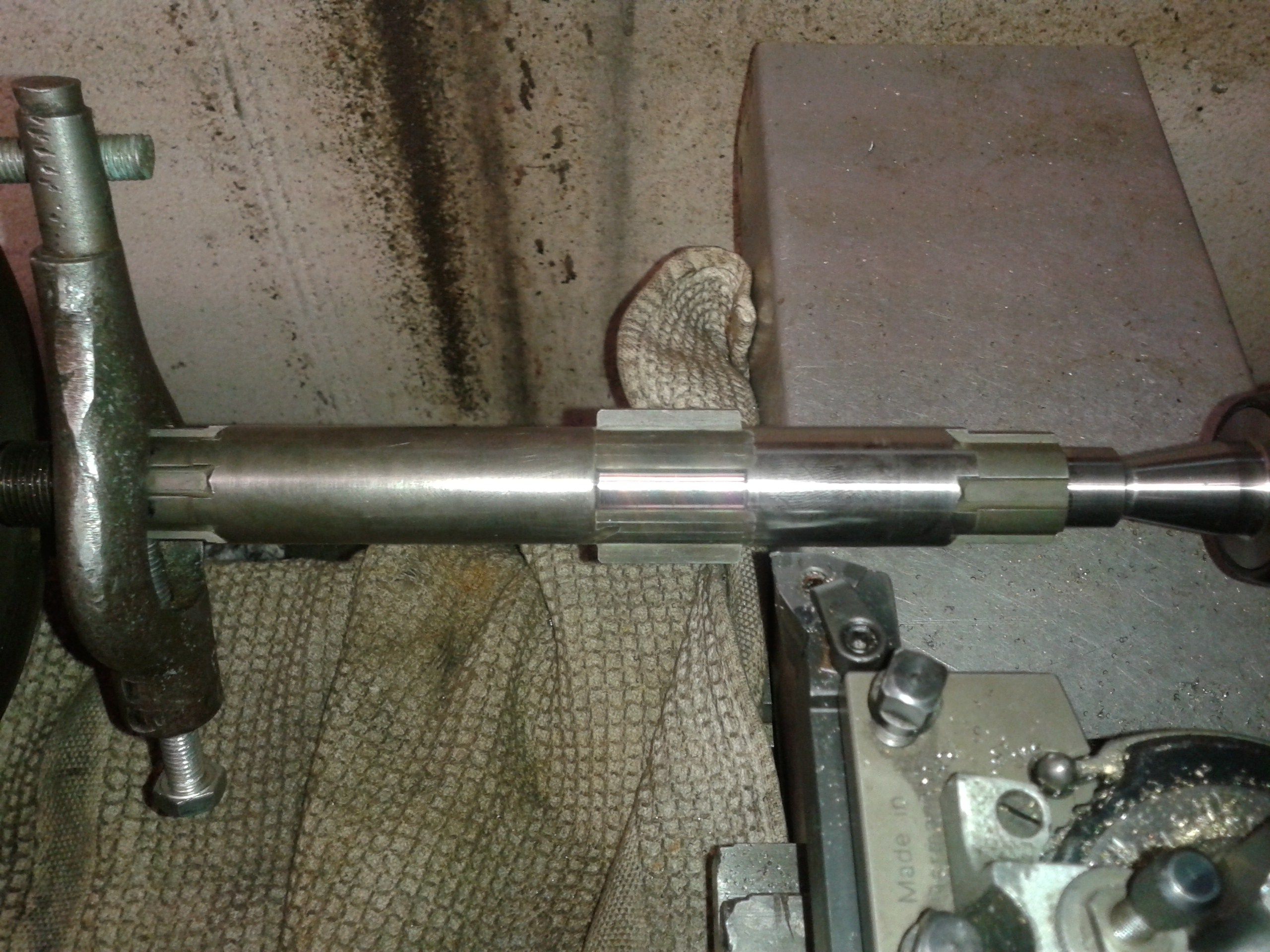
In the end I was able to reduce the runout to +/- .015mm - less than one thou. |
|
|
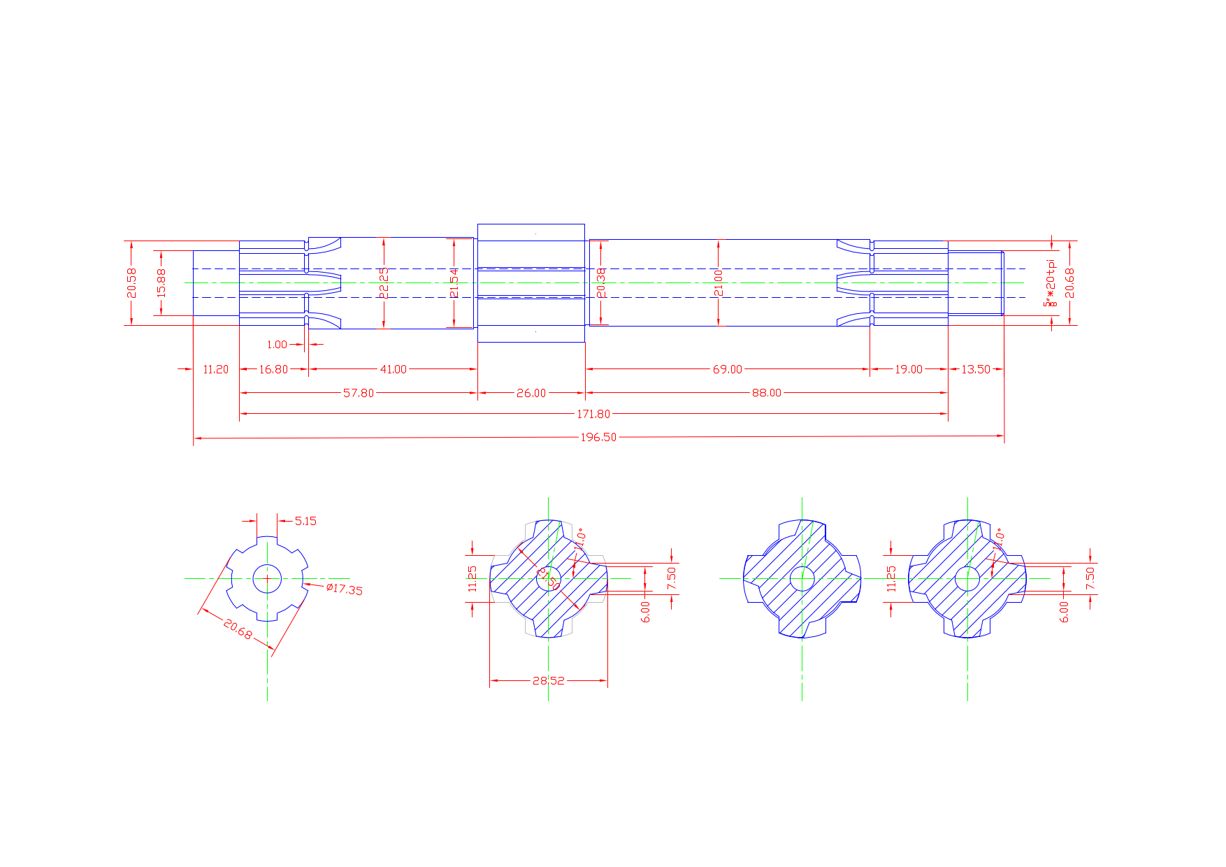
Now the shafts could be machined to their final dimensions.
|
|
|
Again, a simple lapping ring is quickly made up and helps making a good finish and geometry.
|
|
|
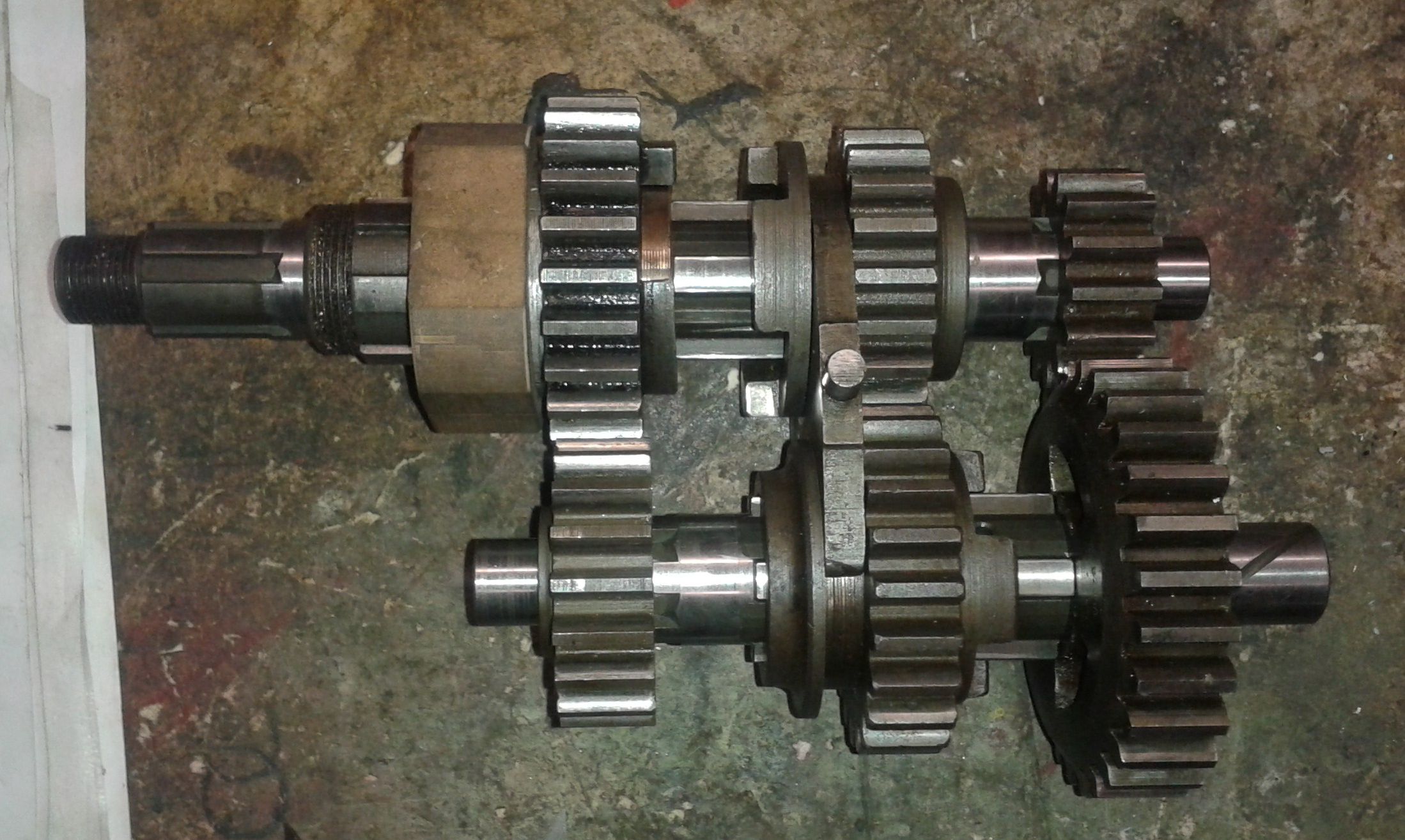
Finally, this is the complete gear cluster.
|
|
Any kind of feedback to
![]() is
appreciated
is
appreciated
(sorry, this is not a clickable 'mailto:' hyperlink. If you want
to write me, please type my address in your mailer. )