Vintage Workshop
Services for Brough Superior motorcycles and their contemporaries
|
Vintage Workshop Services for Brough Superior motorcycles and their contemporaries |
Sturmey Archer gearbox page last update: 04/2022
|
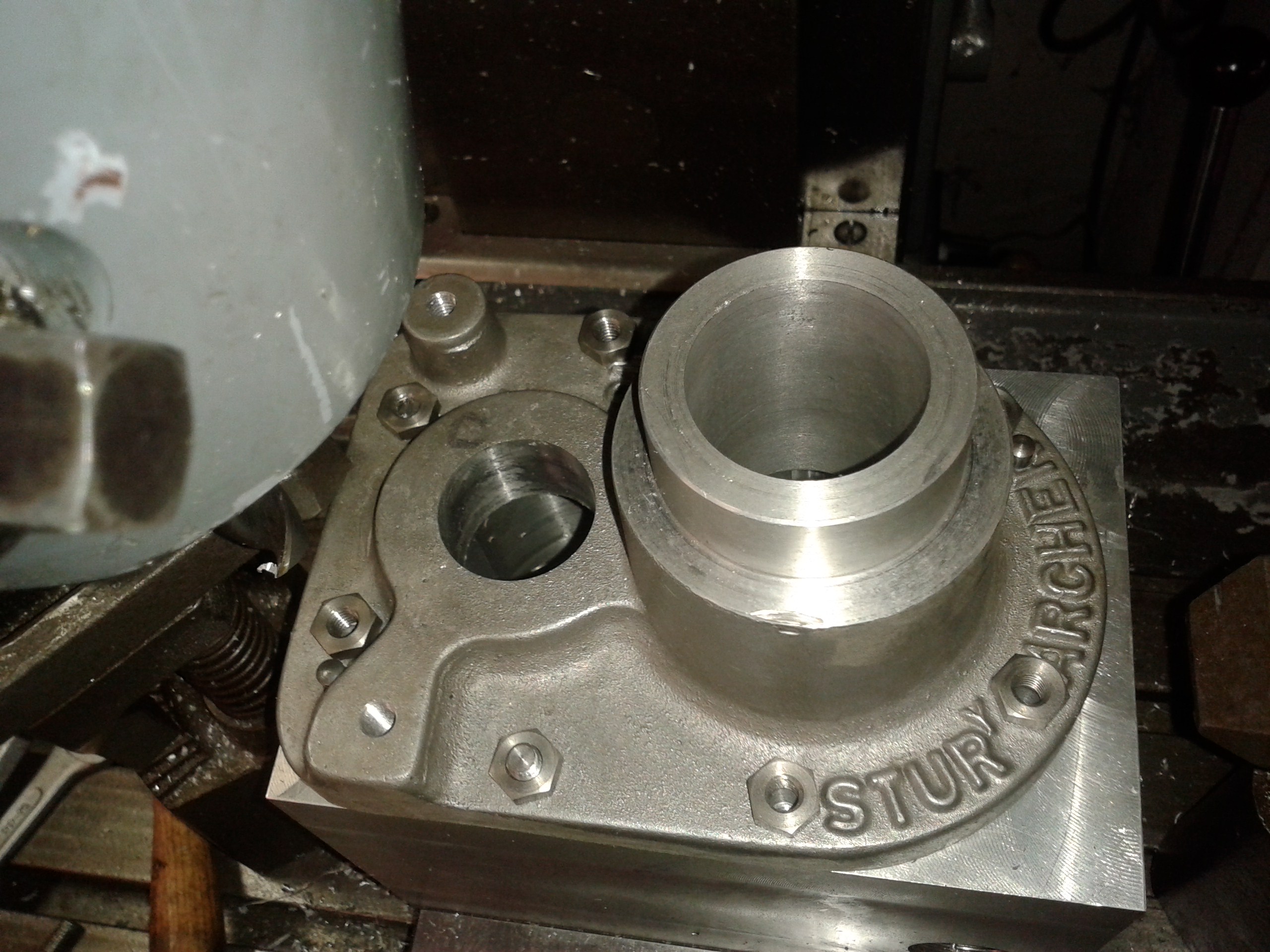
OK, this was now to be the gearbox to end all gearboxes! |
|
|
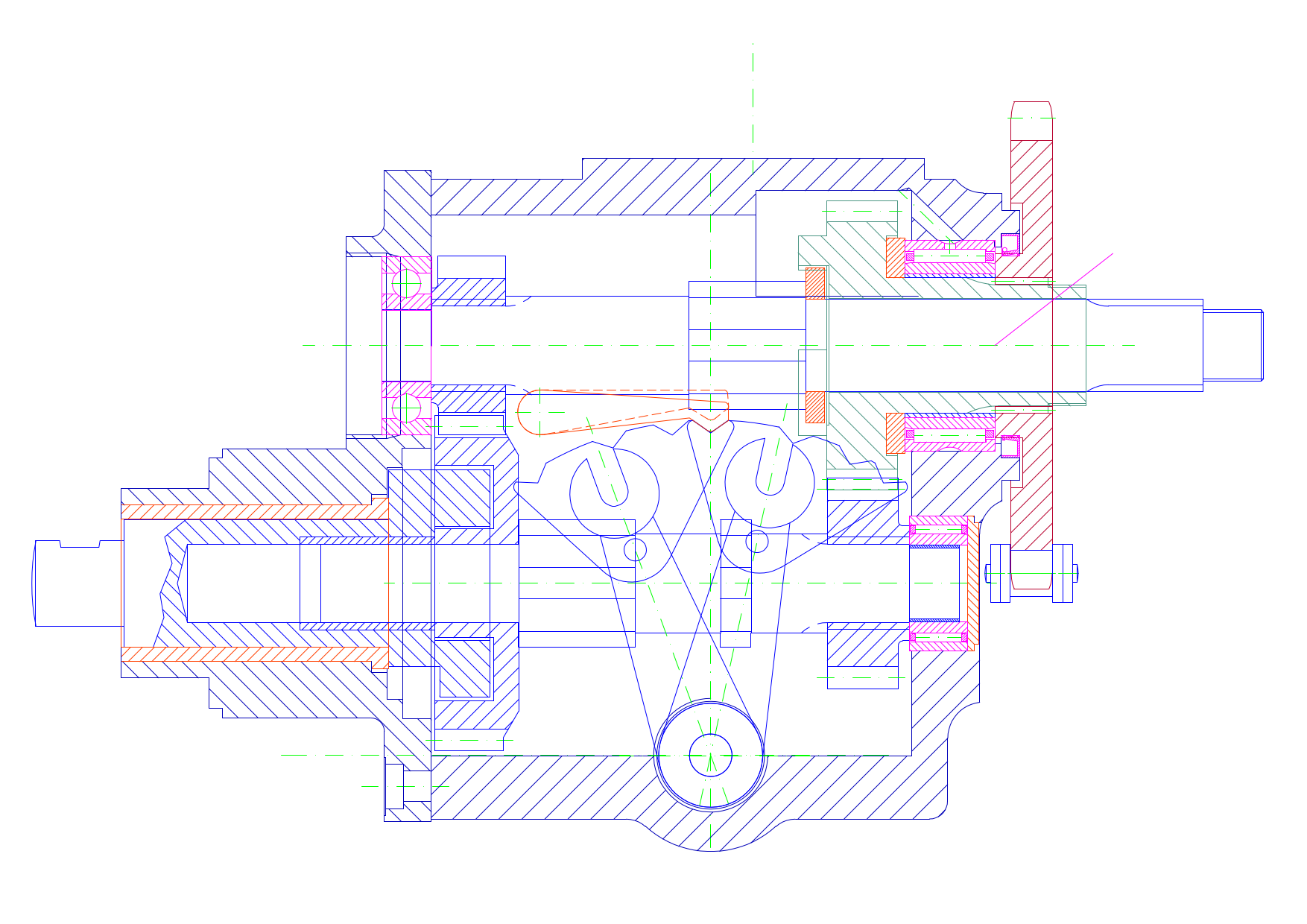
Of course this super gearbox was to have internal gear indexing and heavy duty needle roller bearings on the drive side. My dear friend Vic of Vincent fame is responsible for some of these ideas. In comparison to him, I hesitate to call myself a perfectionist. For instance he was not at all d'accord with the simple plunger indexing the gears and persuaded me to use a pivoting lever instead... |
|
|
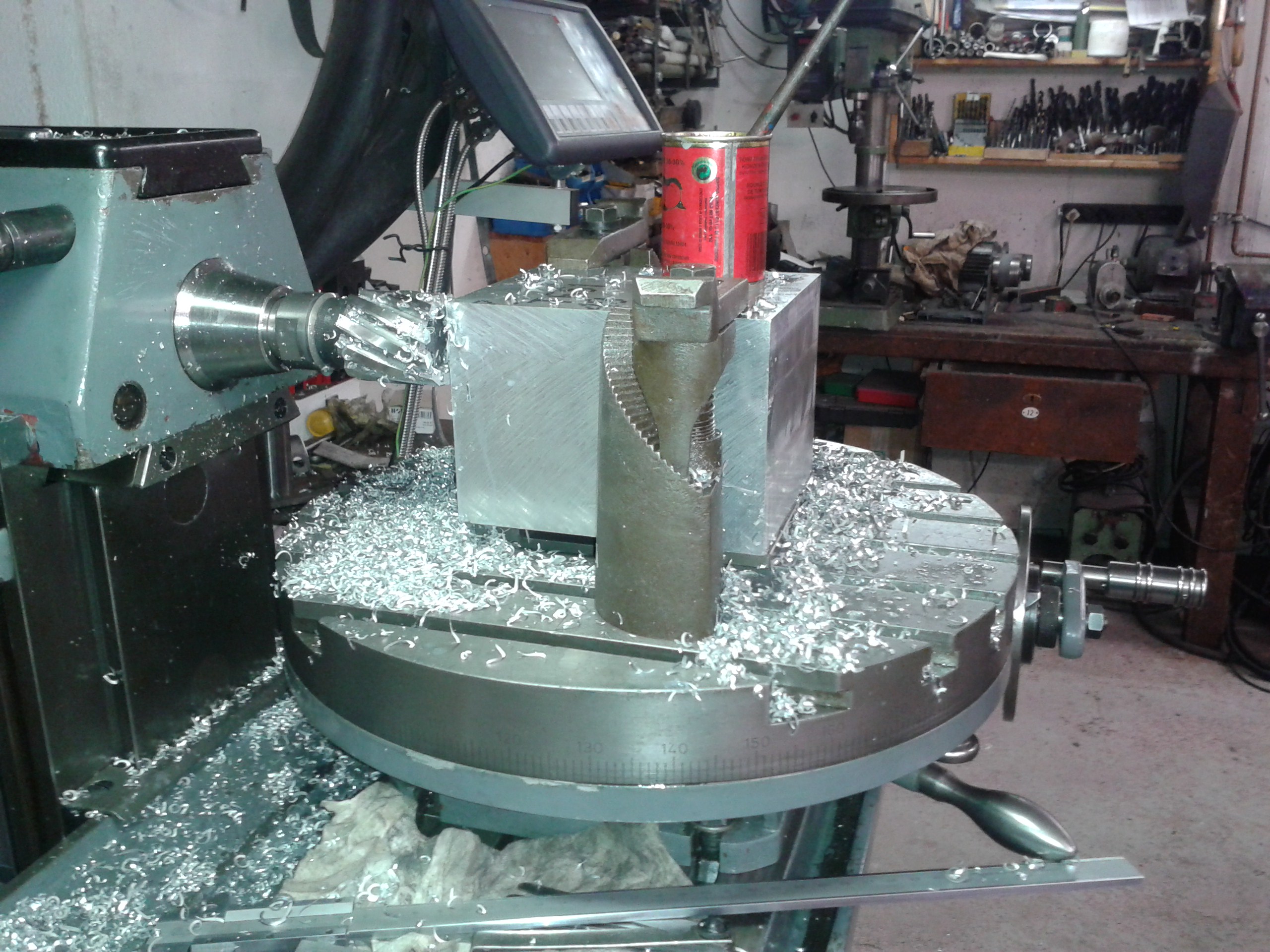
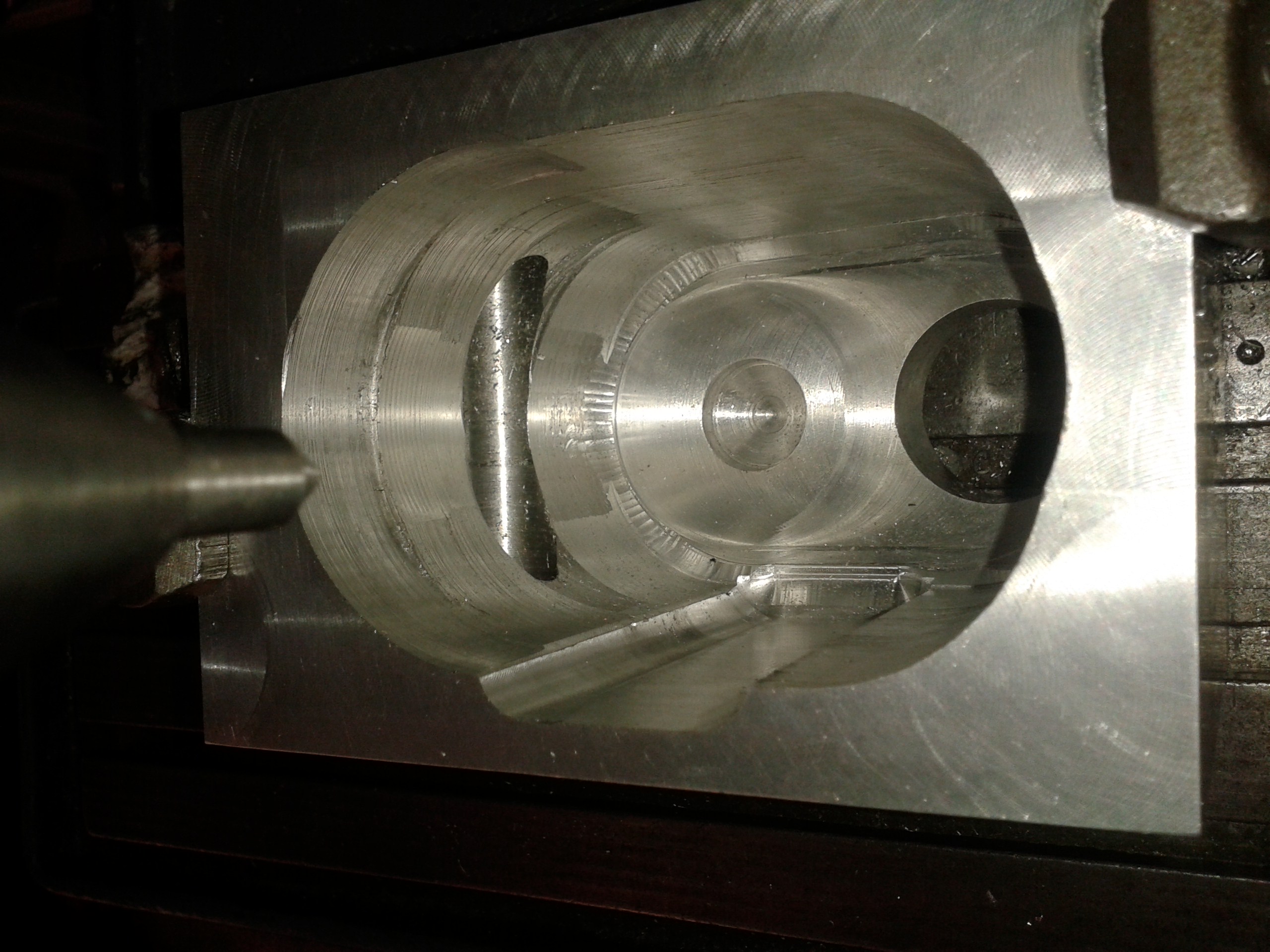
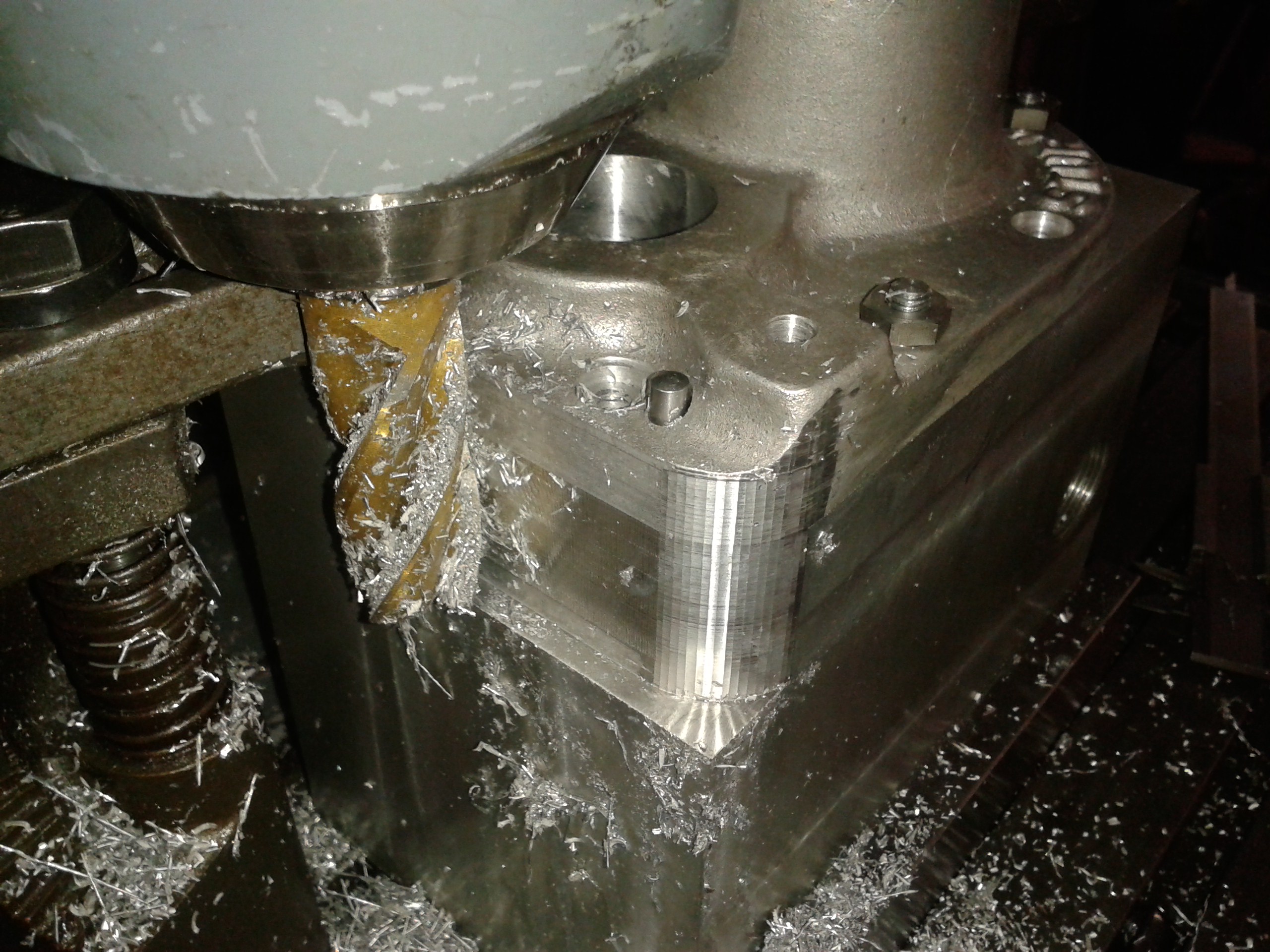
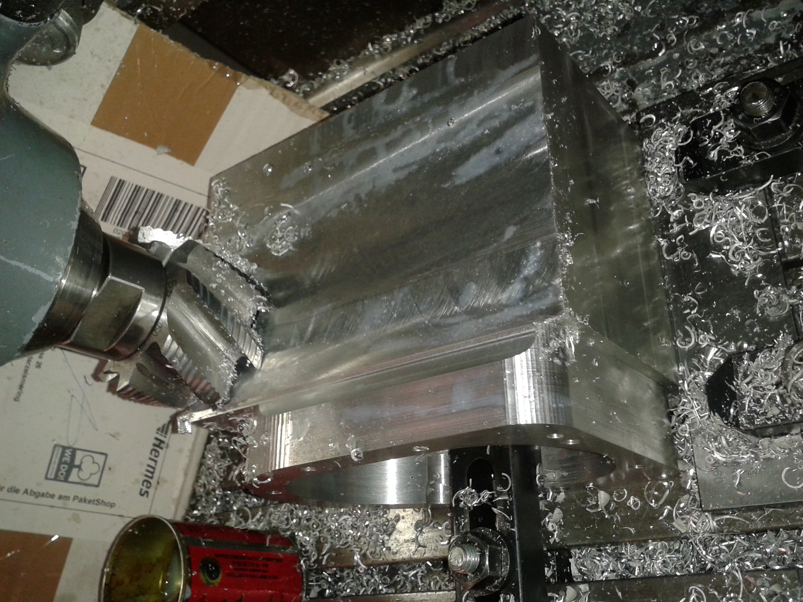
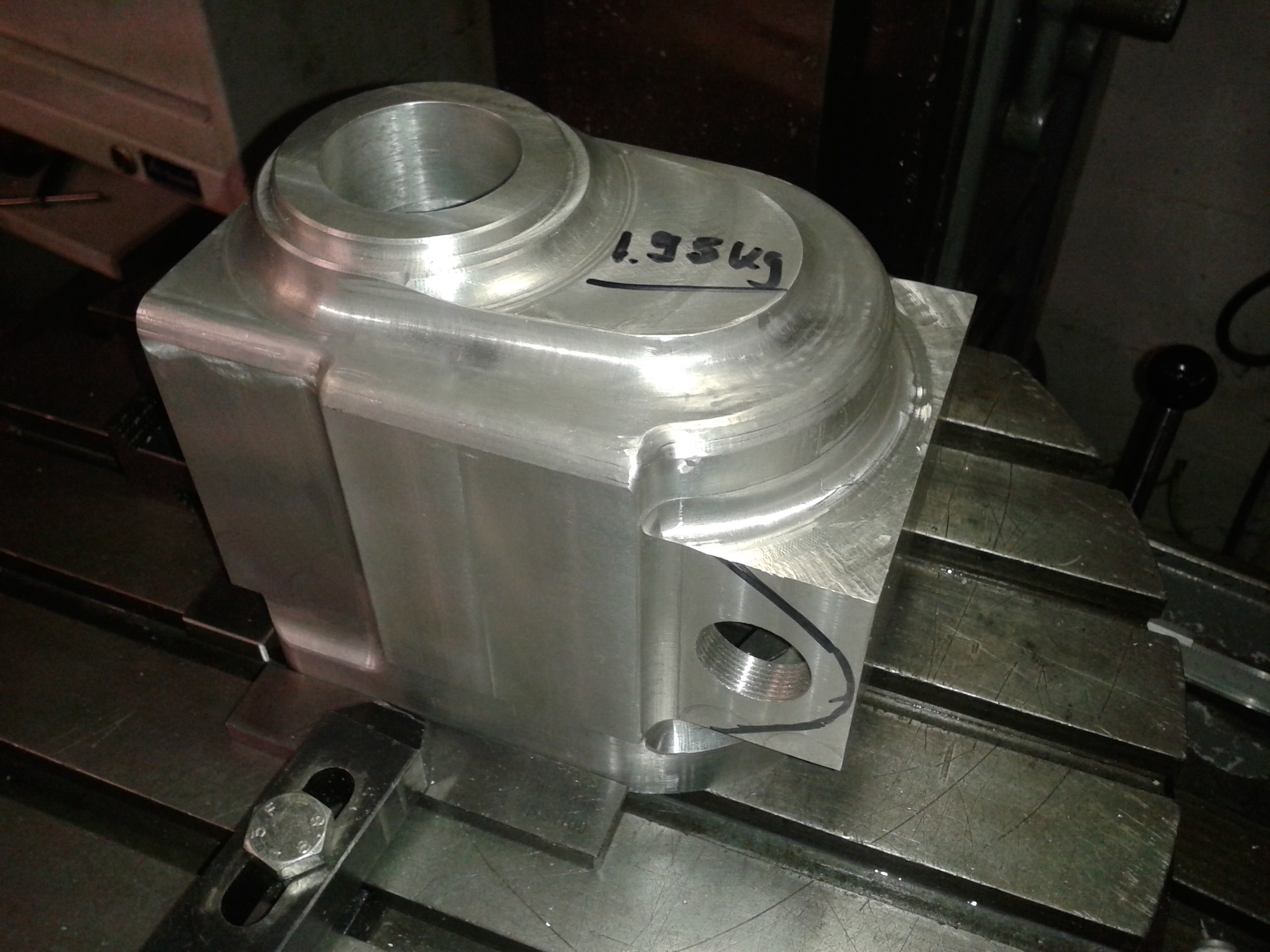
Now the first job that proved tedious was to carve out the big cavity. It brought my poor old FP1 to its limits, even with the motor stalling once! Ok, it might have been a better idea to machine with more speed and smaller cutters... |
|
|
I did not have a sturdy cutter long enough to reach down to the bottom of the trough. So I had to make an extension for a milling arbor... |
|
|
This did the trick and, after 5 days of labour, at least the hard bit was done - well, I hoped. |
|
|
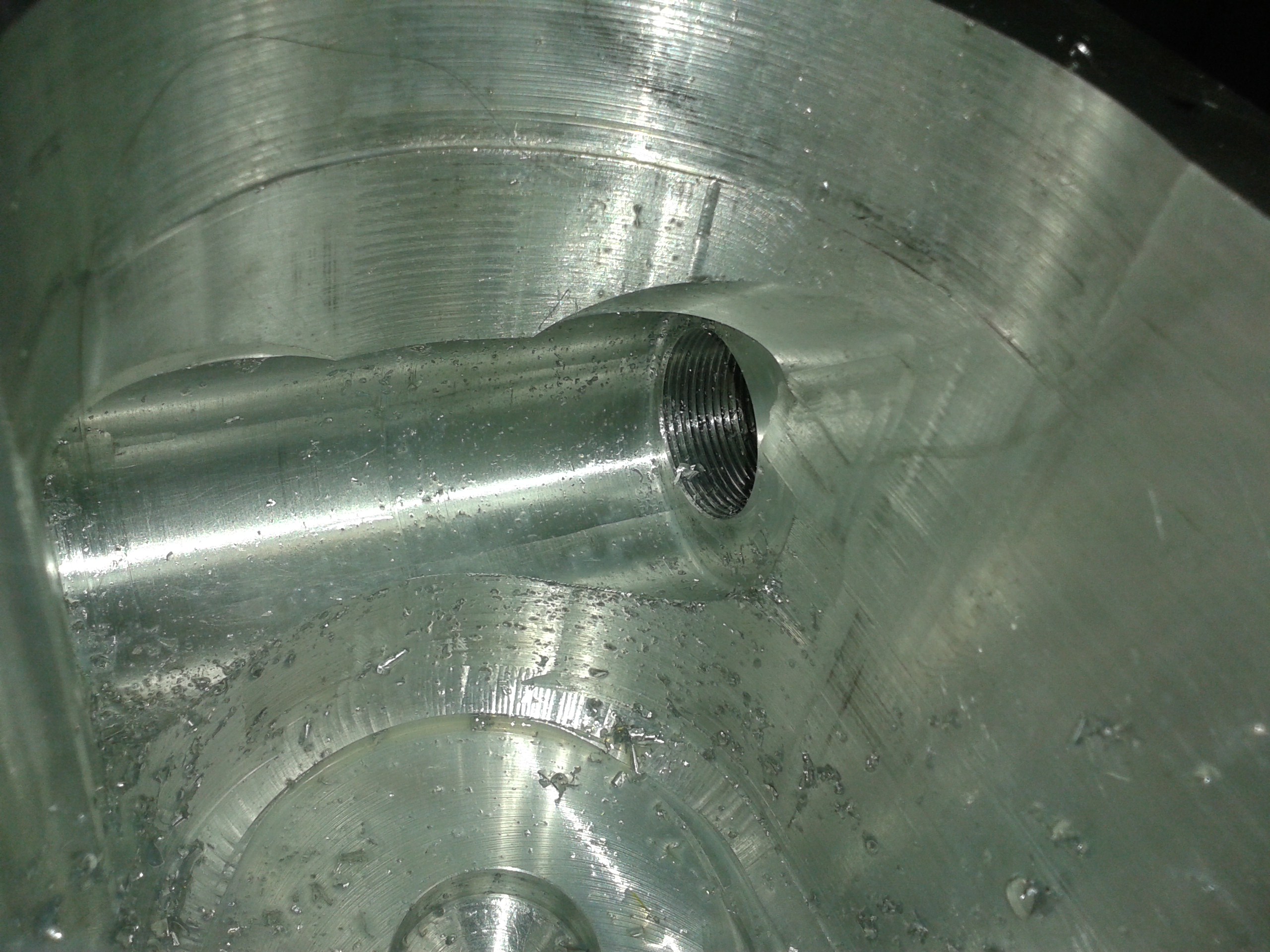
The tunnel for the gear indexing mechanism was not too difficult to machine, although I found later that I still needed to enlage it a bit. |
|
|
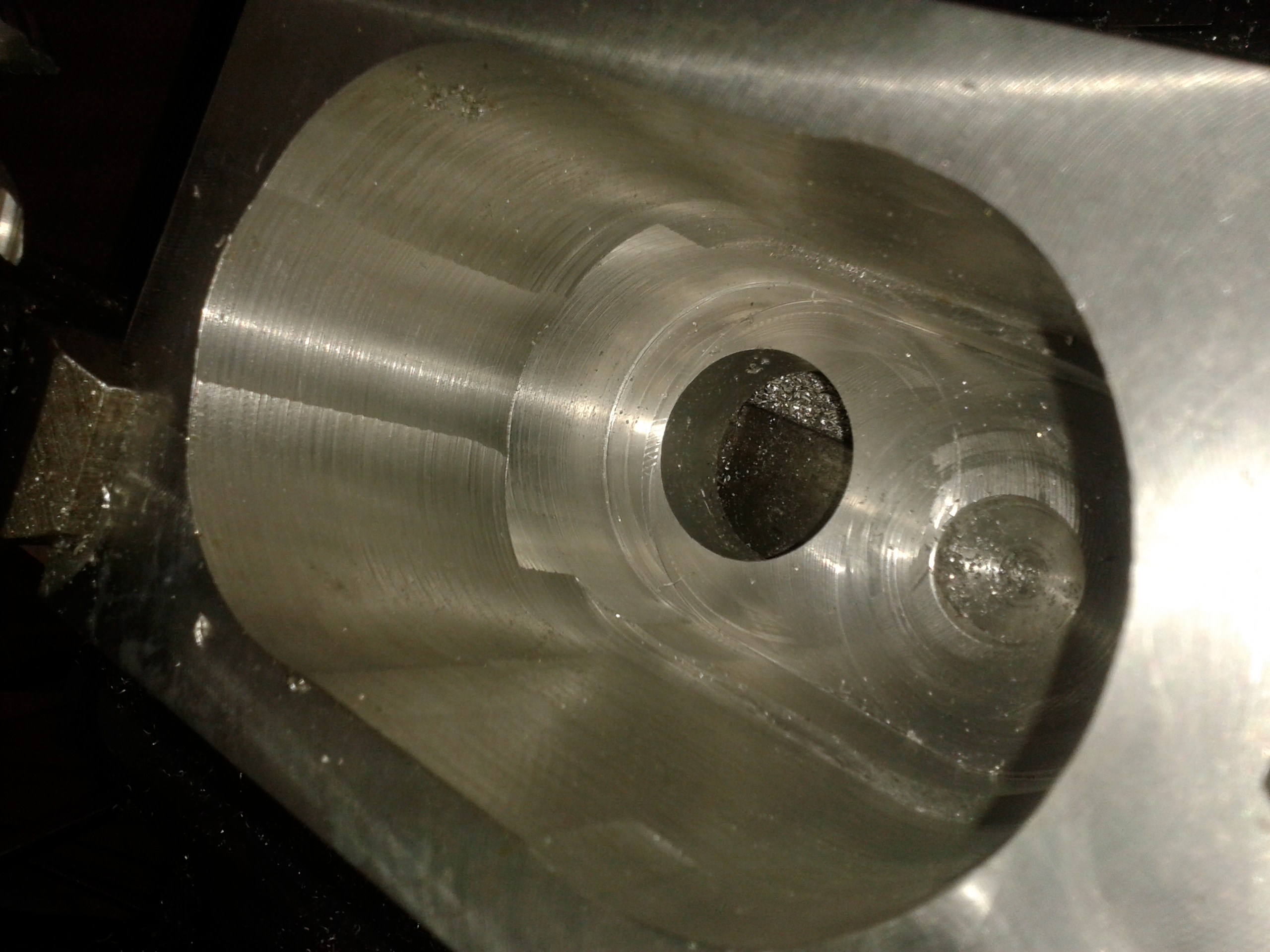
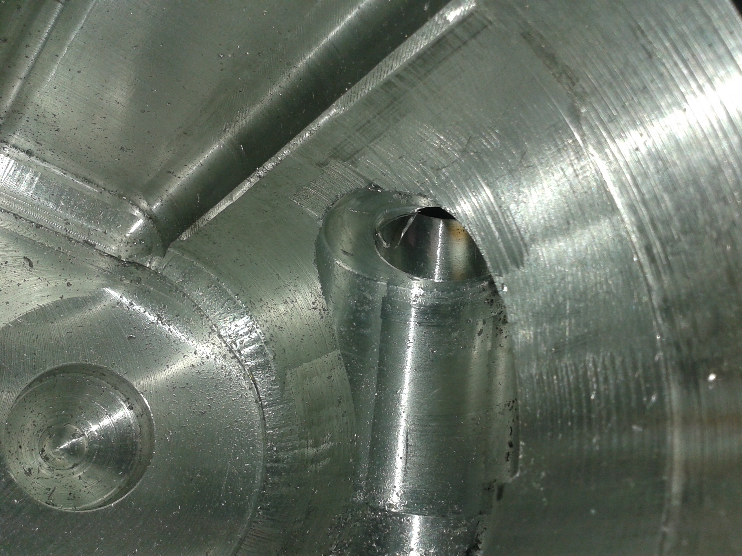
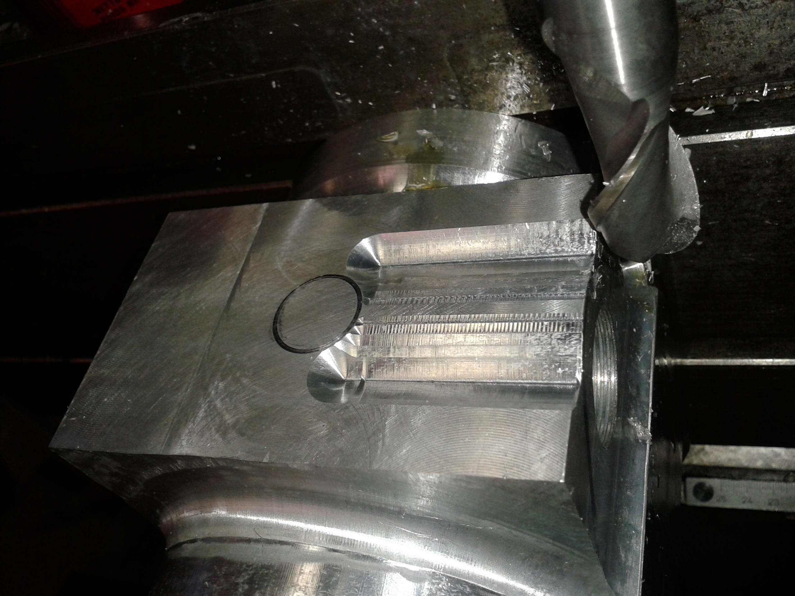
Boring out the space in which the gear selector for turns was something different, though.
That one is quite a bit wider inside and you can only machine through the 1"x20tpi thread holes...
|
|
|
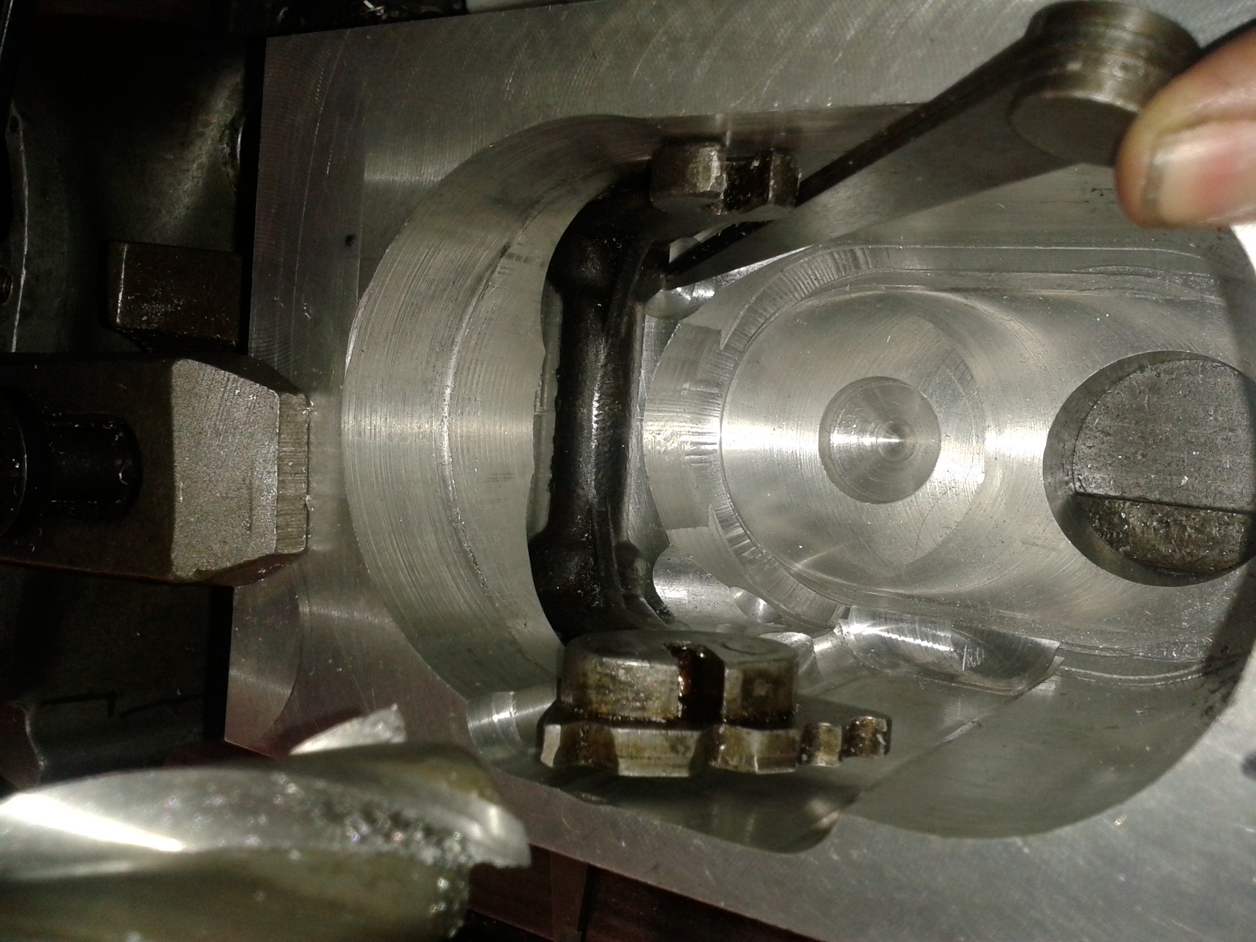
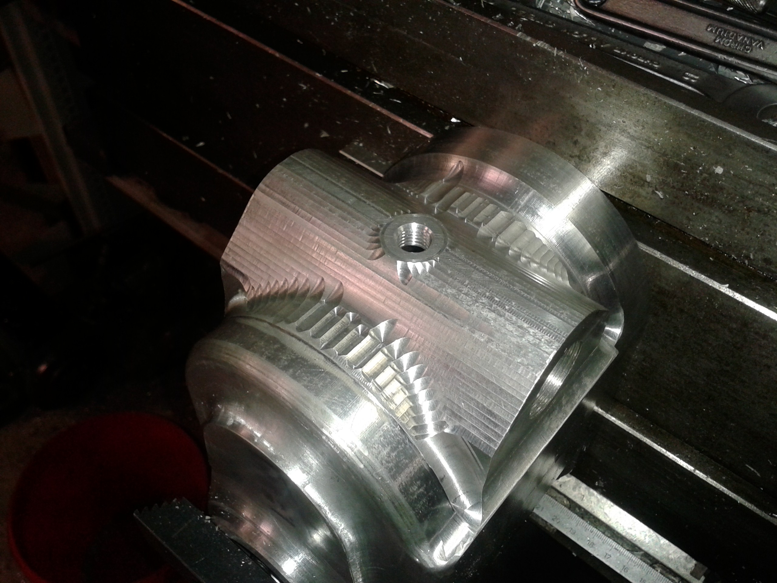
Still, the selector for needed some more room to swing about. This called for some quite intricate machining, running the feed on two axes simultaneously. I hesitate to admit that this went awry in one of the bottom side reliefs - bear with me for not uploading a picture of the defect.. :-) |
|
|
Now, finally, the selector fork had plenty of room to move! |
|
|
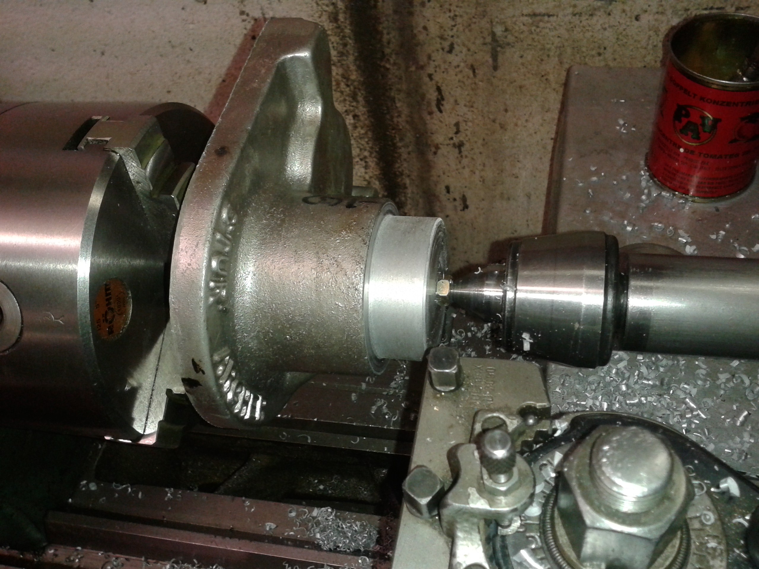
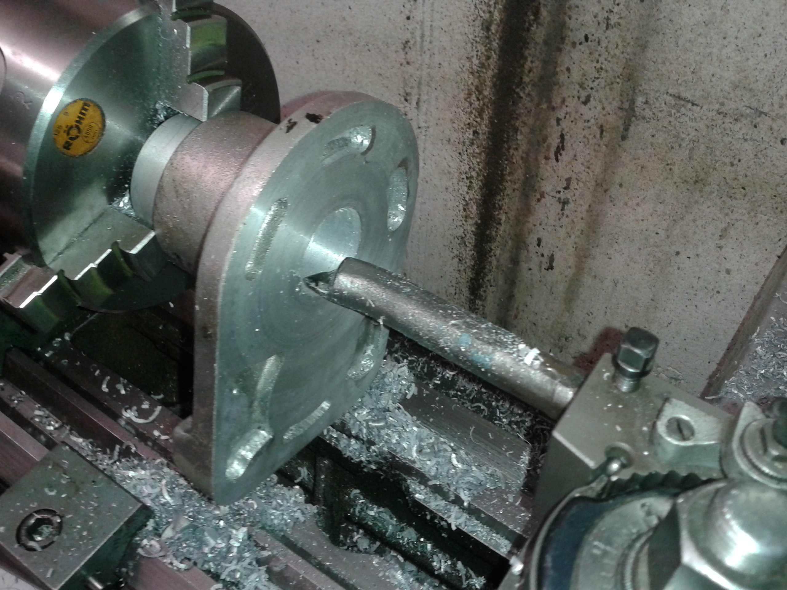
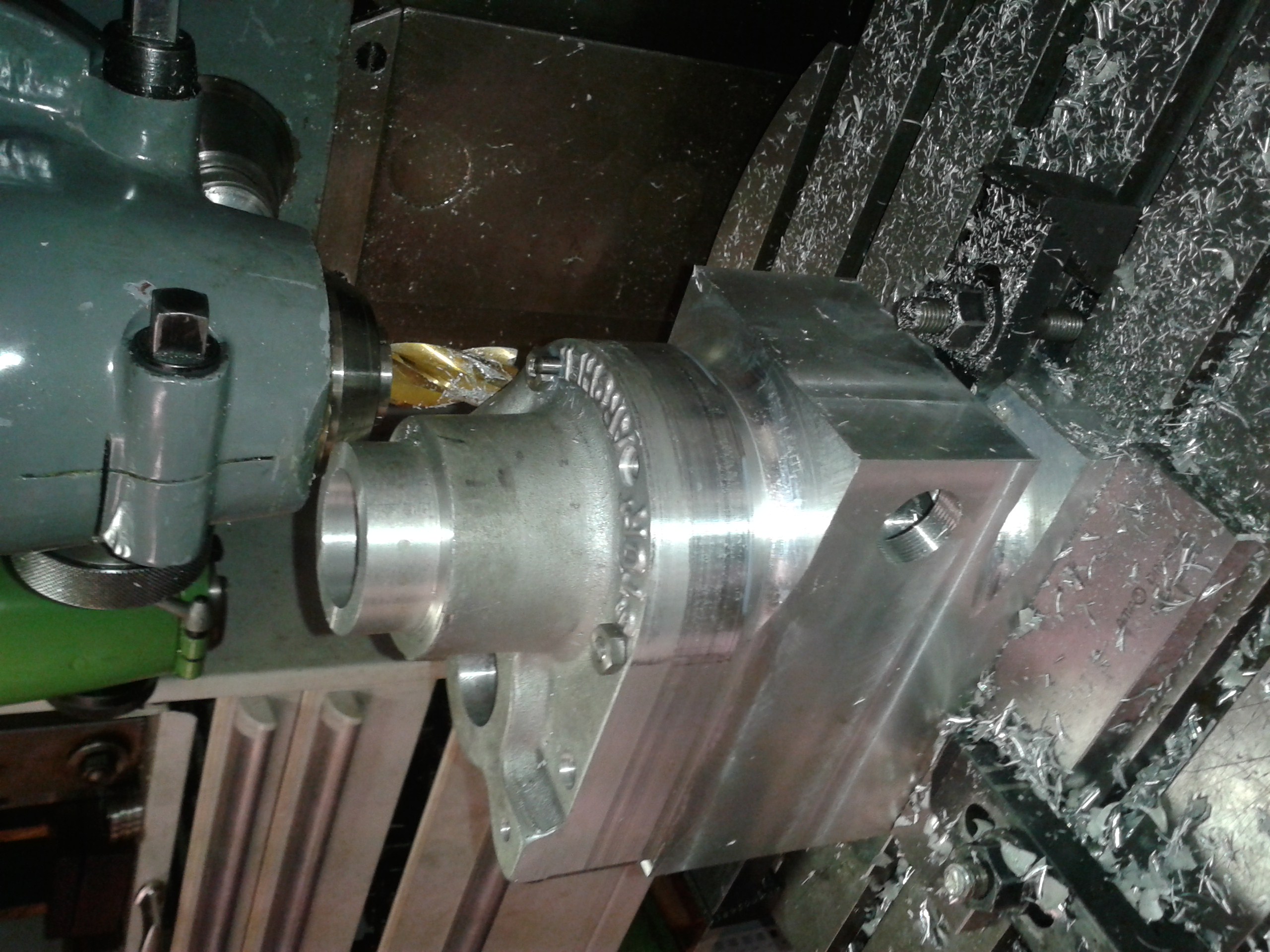
Next, I needed to machine a cover. I still had a few castings from an earlier batch of covers I had made. These have the long, thick kickstart boss for the later bikes with both exhausts on the right hand side, but cutting off excess material is easier than adding some. I first machined a little step on the inside surface, than held the piece on that to machine a bit on the kickstart boss on which I could firmly hold the bit. |
|
|
Then machining the bore for the kickstart shaft bush and the different recesses was straightforward. |
|
|
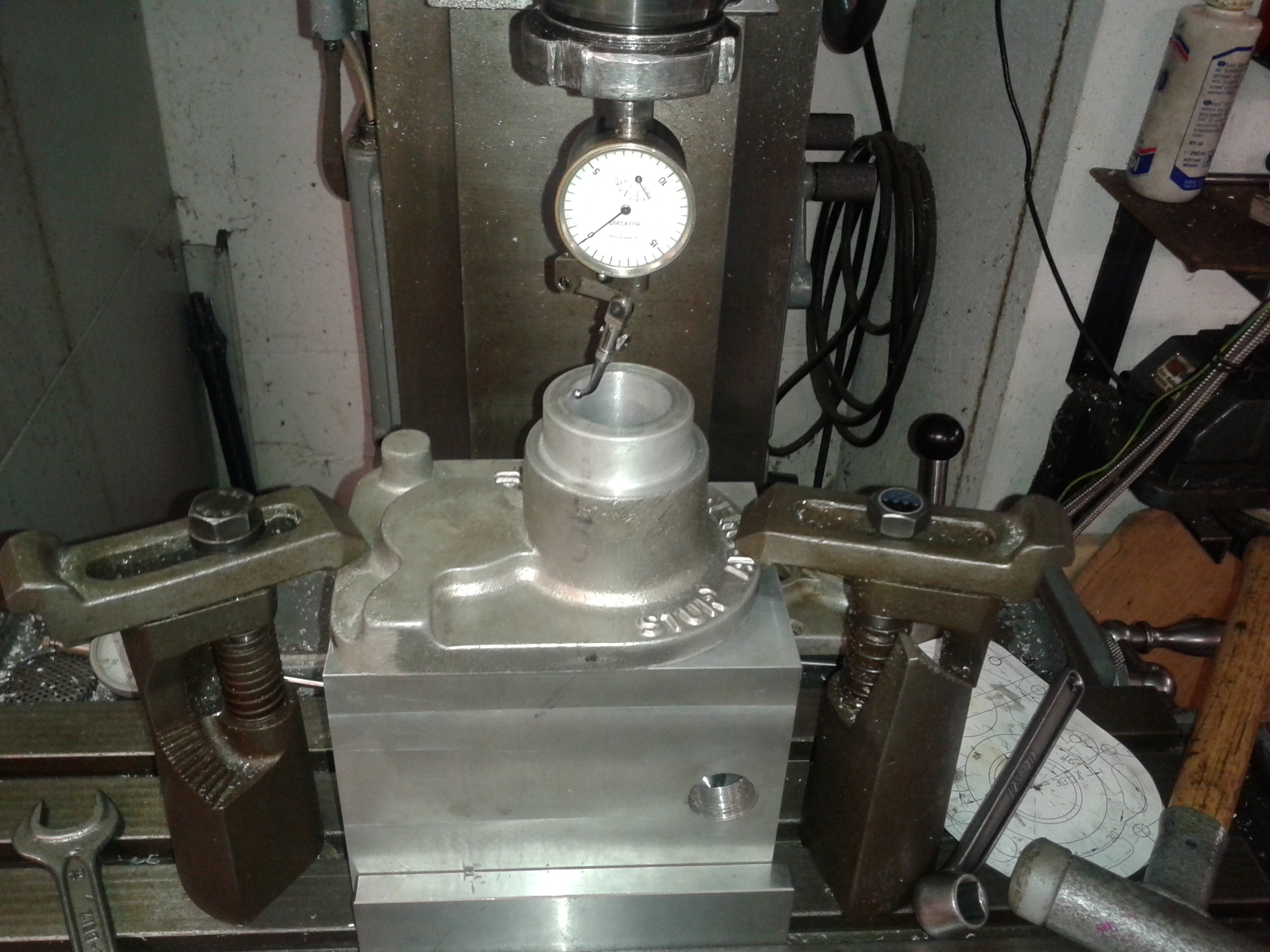
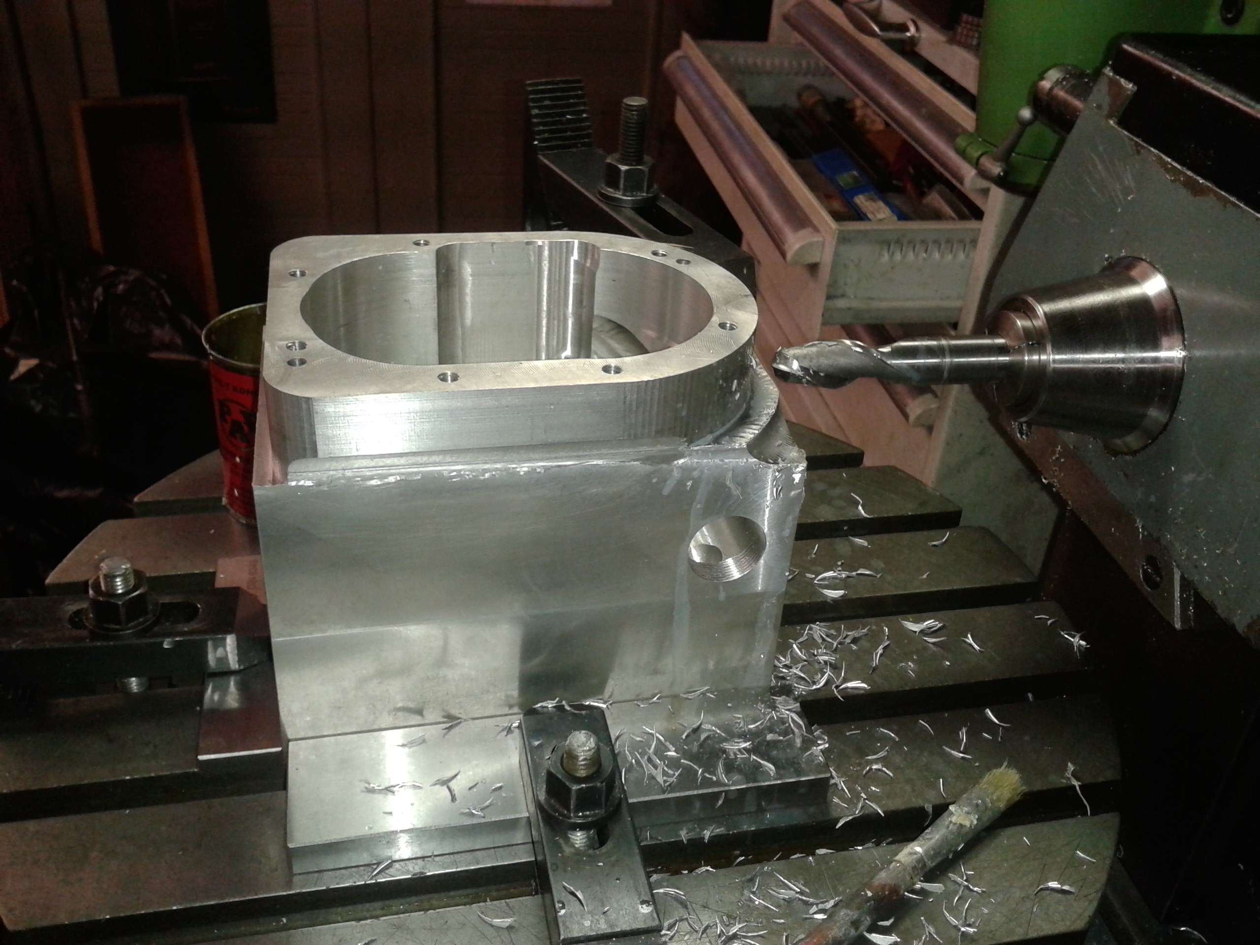
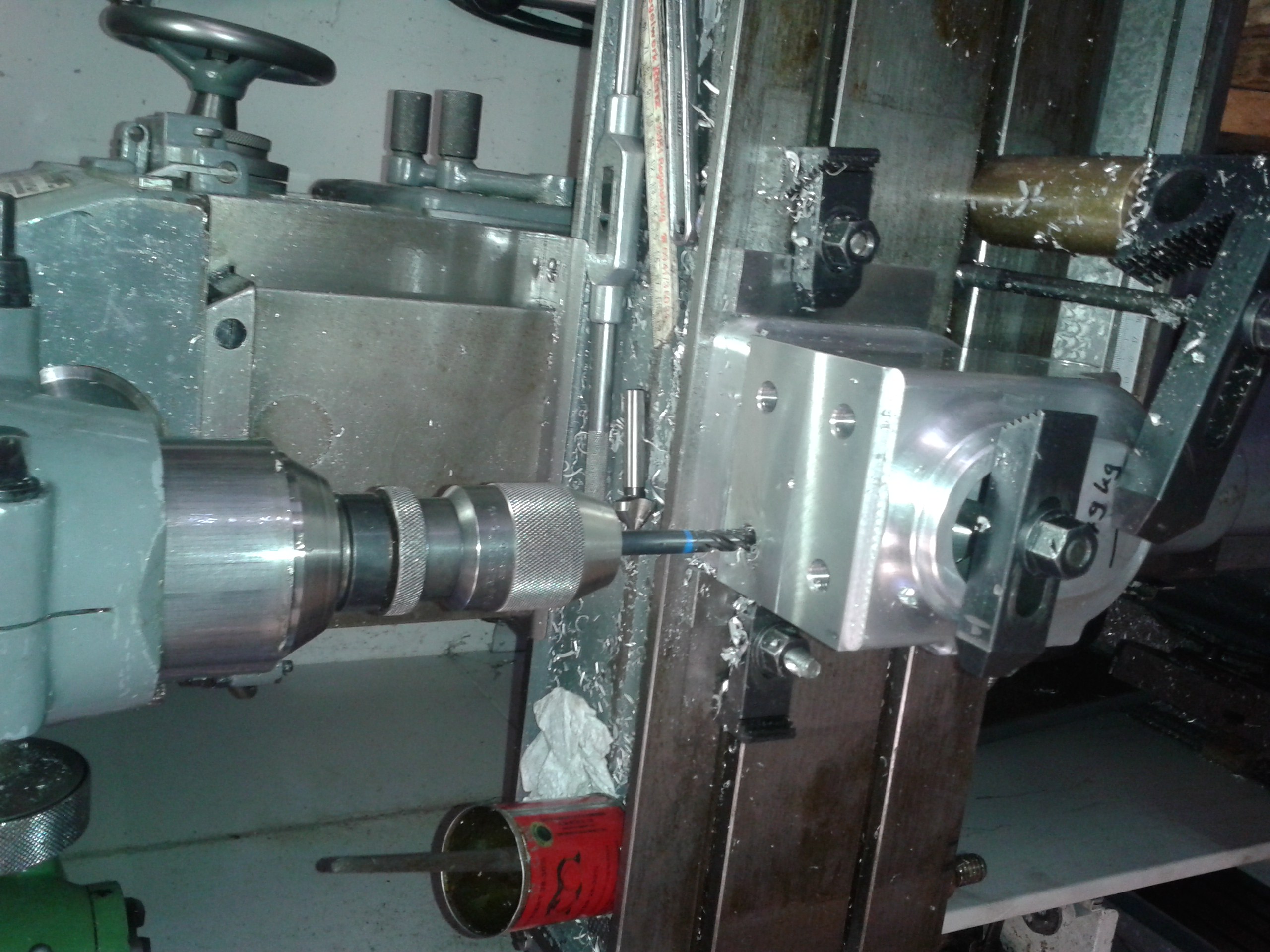
Next, I carefully aligned the cover on the case. This allowed me to drill the bolt holes through the cover and into the case. I have also added two pegs to accurately locate the cover - I never understood why Messrs Sturmey and Archer relied on the studs with their fairly inaccurate positions to take care of the alignment. |
|
|
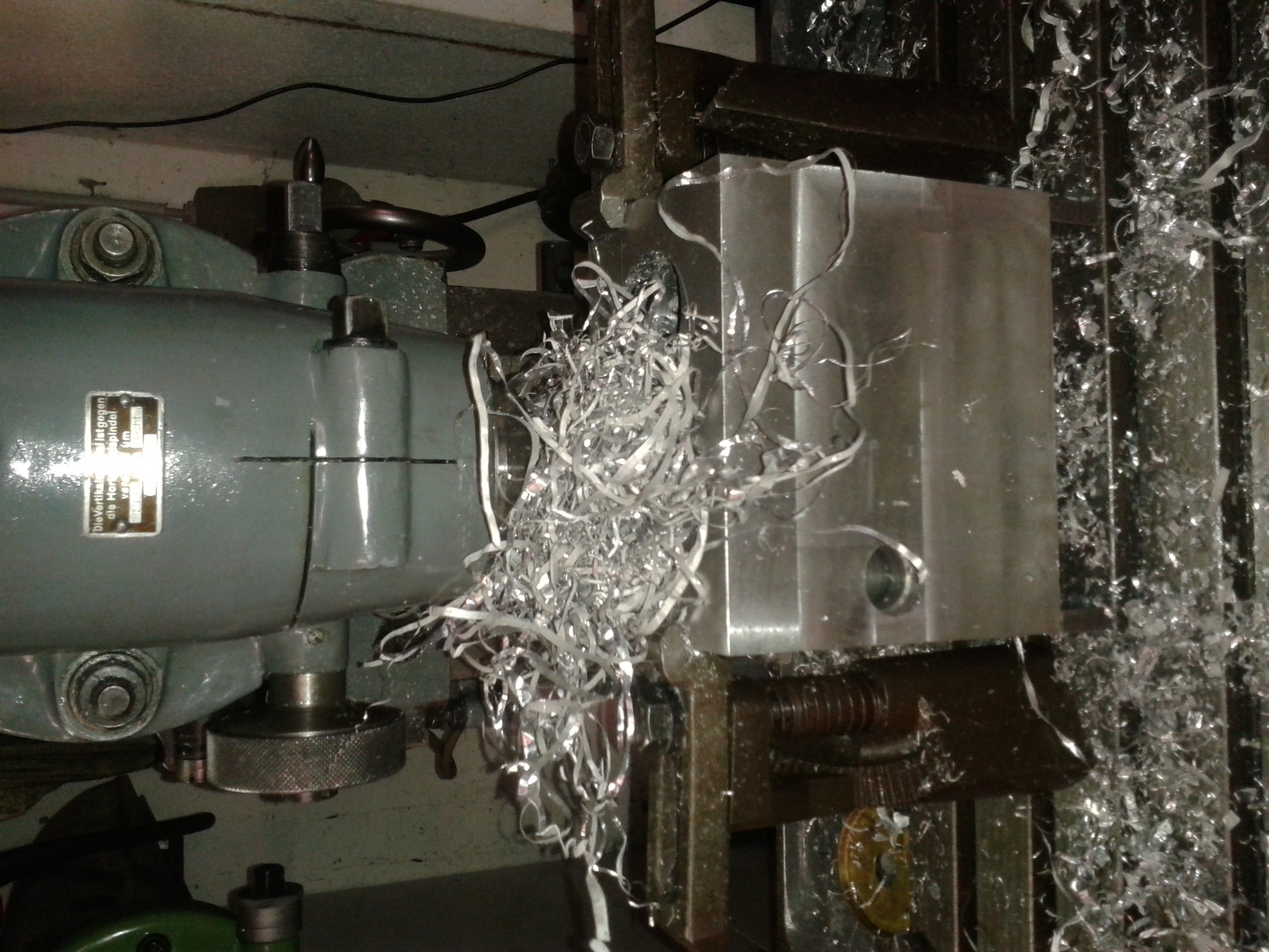
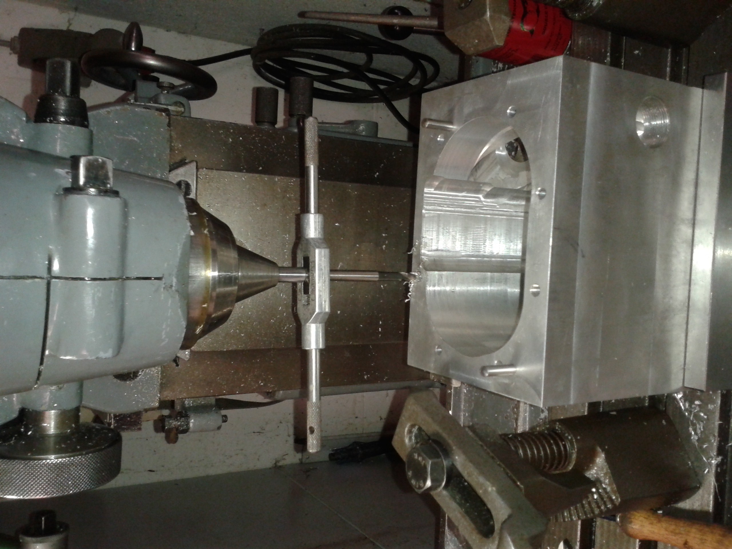
I usually don't cut small threads with the milling spindle. My milling machine has no reverse, and if you use a low gear to go slowly, it takes a long time to stop when you switch the motor off. Altogether this results in a high risk to break a tap, especially on blind holes like these - and what a hassle is it to go out and have the broken tap spark eroded to save your piece of work... So I usually cut such threads by hand and use a spring-loaded point to keep the tap in proper alignment. |
|
|
I made the special Sturmey nuts and the recesses for them, but bear with me - I did not use the odd Sturmey thread which is slightly bigger than 1/4"... |
|
|
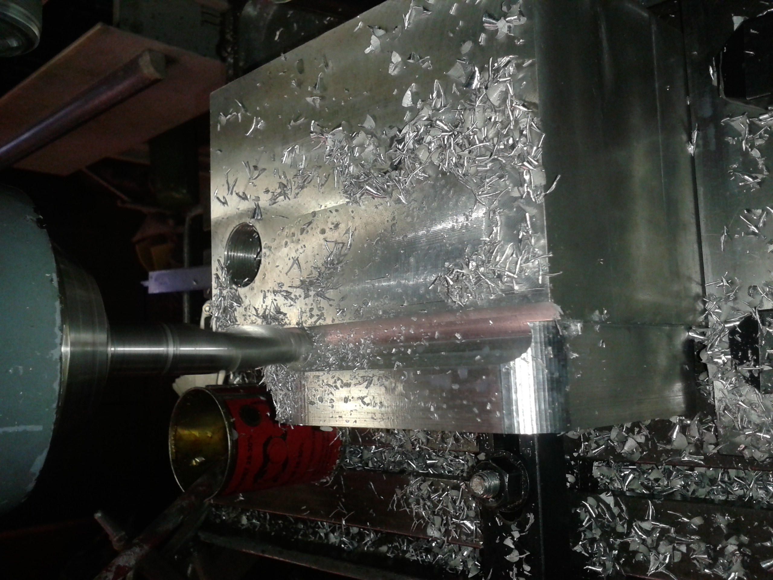
Now, with the cover bolted to the shell, I could machine the contour of both together. For the rounded corners I used the radius function of my Chinese DRO - a quite handy feature. |
|
|
Same for the big radius on the lower end. |
|
|
The transition to the smaller width on the sides were made with a 16mm ball nose cutter... |
|
|
... and the side again with a shell end mill. |
|
|
Then, getting fed up with the slightly cumbersome radius function I put the shell on the rotary table to make the smooth transition that follows after the kickstart side contour. |
|
|
This allowed me to clean up the steps on the contour as well. |
|
|
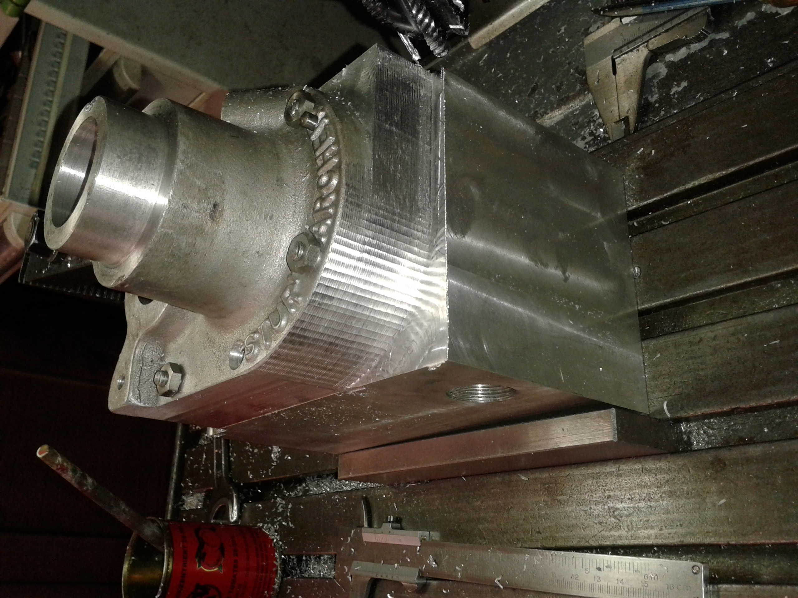
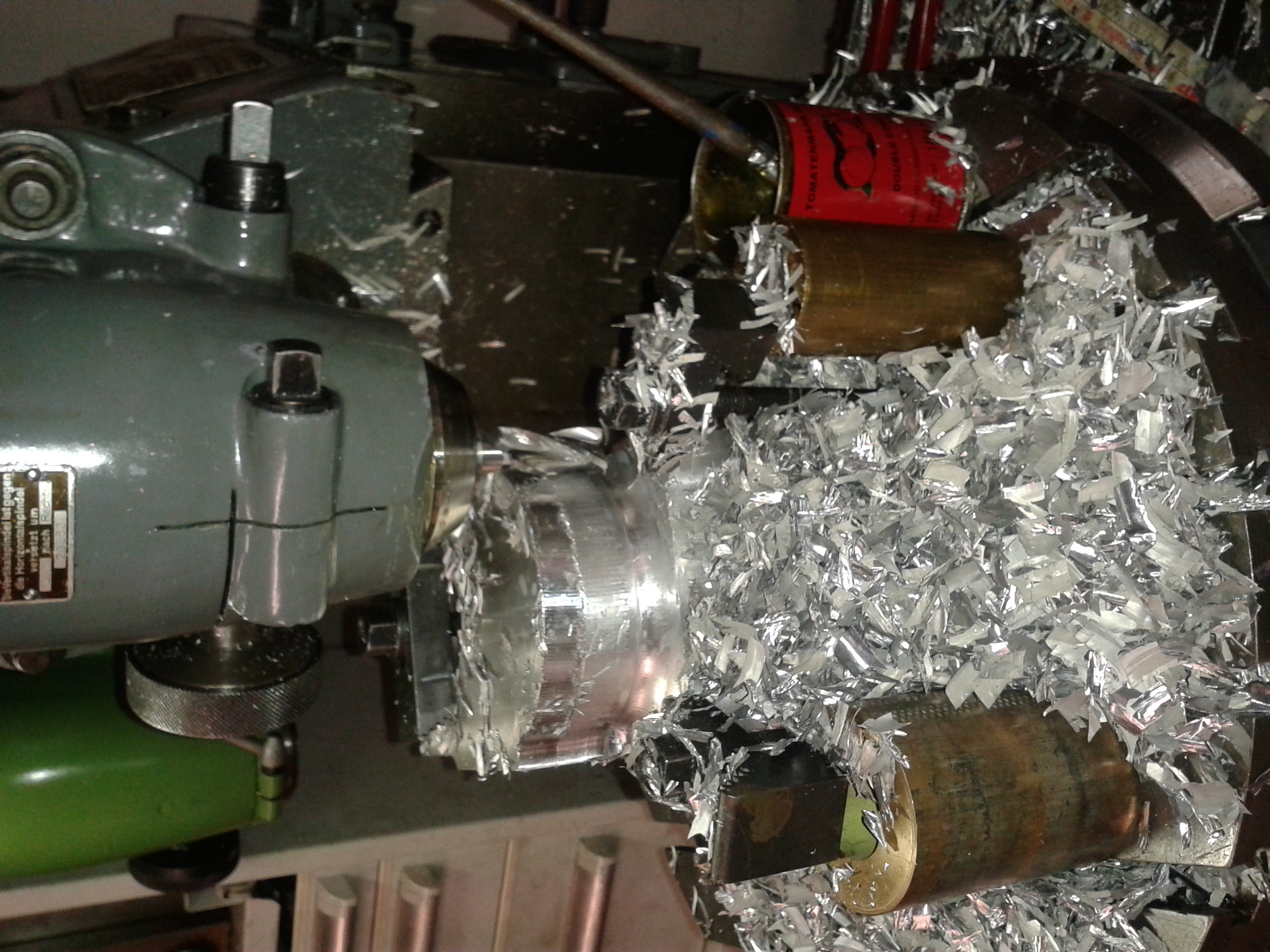
The whole exercise wanted repeating on the drive end side. The pic illustrates nicely how much expensive aluminium is converted into useless swarf in the process! |
|
|
Machinig the drive end contour was also clearly a rotary table job, albeit with the work once positioned to the centre of the layshaft and then to the mainshaft. |
|
|
Now, things are getting interesting: the contour around the gear selector fork is a bit intricate. I studied the shape and wrote a little Excel sheet, using basic trigonometry to calculate the milling paths. I had also decided to move the oil drain plug away from it original position which strangely does not allow to completely drain teh case. |
|
|
This worked quite well - ok, apart from a few minor glitches which were due to lack of concentration when reading my values from the Excel printout. |
|
|
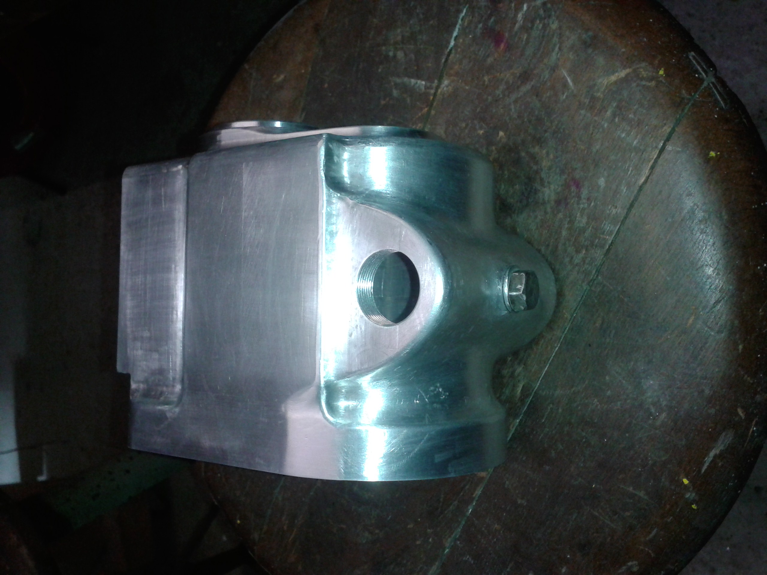
Cleaning up the machining steps was not too bad a job, though it required a certain amount of concentration. If you should wonder why the bottom extension is wider than on an original LS type gearbox...well, being a bit impatient I had made too much room for the selector fork to move inside, so I had to replicate this shape on the outer contour I am afraid... But anyway, I am fairly pleased with my "casting" |
|
|
Machining the top and cutting the stud threads was a quite straightforward job now. |
|
|
... to be continued... |
|
Any kind of feedback to
![]() is
appreciated
is
appreciated
(sorry, this is not a clickable 'mailto:' hyperlink. If you want
to write me, please type my address in your mailer. )