 Vintage Workshop
Services for Brough Superior motorcycles and their contemporaries
|
Vintage Workshop Services for Brough Superior motorcycles and their contemporaries |
KTOR cylinder heads page last update: 8-11-2002
Well, casting a cylinder head requires an elaborate pattern and an even more elaborate core box!
So I did never think of doing this myself but ordered a pair of head castings from MFC. Again, they can be found at http://www.japbits.co.uk .
Unfortunately the Cullingworth family went trough all sorts of disasters with the production of these heads: the foundry delivered a few poor castings, then they closed down for refurbishment, then the opened again to deliver a few more unusable castings just to close finally. But now the Cullingworths have found a good reliable foundry, and I received a pair of castings.
So all I have to do is machine them. I
knew this was not going to be easy, but I never knew it would be such a lot of
work!!!
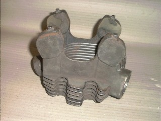
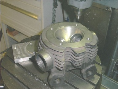
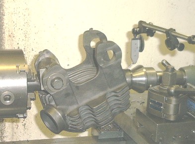
| This is how they come. Well done MFC! |
|
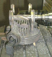
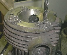
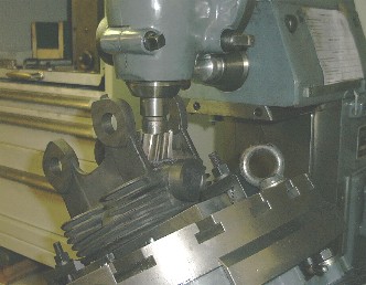
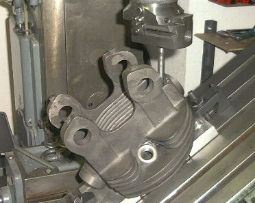
| So, first I roughly aligned them and drilled a 1" hole through the dog
ears and milled one side of the ears flat. No, this was not done in 15 minutes.... And, if you noticed the small
pimples on top of the dog ears: A very good idea by MFC! |
|
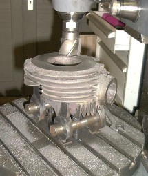
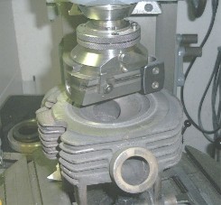
| Here you can see why I needed the big holes: clamping it down by the
fins would not be a good idea...
Now you can machine the gasket surface. |
|
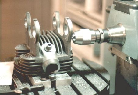
| Next, the spigot. Easy job. Oh, I forgot to mention: I am doing all of this on a rotary table! |
|
| Well, then I thought I wanted a smoother gasket surface. Have you ever
seen a Wohlhaupter boring head with automatic radial feed in operation?
I think this is one of the most clever tools that has ever been made! |
|
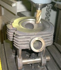
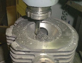
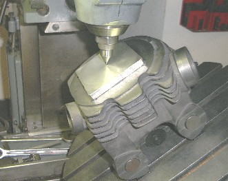
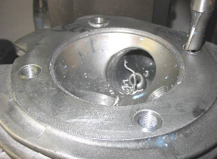
| Now, here is a lot of excess material in the combustion chamber.
As I did not fancy clamping the head onto my lathes faceplate (yes, I am a coward, I know...) I decided to machine the sphere on the mill. Step by step, not as bad as it sounds, but I had to write a little computer program to print the traversing data... |
|
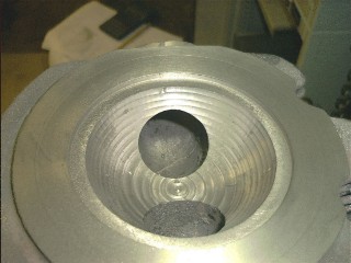
| That is how it looked after the first go. |
|
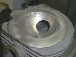
| The second one was done in finer steps, however. |
|
| now, we need bolt holes... |
|
| ...and threads! |
|
| But now, things get interesting! The Wohlhaupter is not only a boring
tool, of course you can also machine on the outside. This is how I machined
the exhaust port stub.
No I do not need a thread on it, as I intend to use the big alloy coolers which are clamped on! |
|
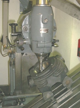
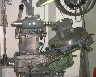
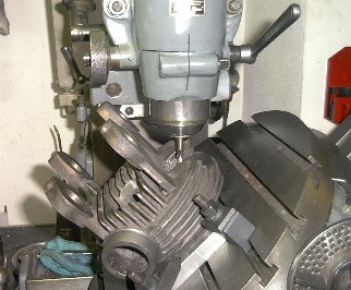
| And even more interesting!! This is how I intended to machine the valve guide bores and valve seats. The FP1 is an ingenious little machine, but it is too small; unfortunately tilting table and rotary table combined took up too much height! |
|
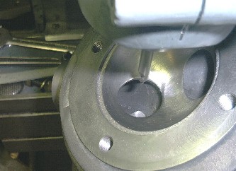
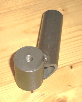
| When it is all set up, you need to find the centre of the combustion chamber sphere. As this point is somewhere in the air, you need a little jig to get hold of this position. |
|
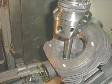
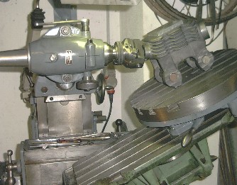
| A new day, a new chance: Now I left the rotary table out. Needless to
say I had to re-align everything and measure the centres. And I set it up
three times until I found how it really works.
But then I was eventually able to mill a flat in the port and centre drill the valve guide bore. |
|
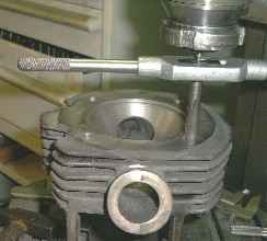
| Drilling and reaming it was relatively straightforward, then. |
|
| And I machined the valve seats in the same setting, again using my
beloved Wohlhaupter head. Oh yes, due to not using the rotary table, I had to set everything up afresh before I could continue with the second valve! |
|
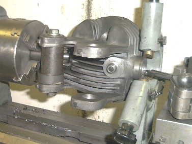
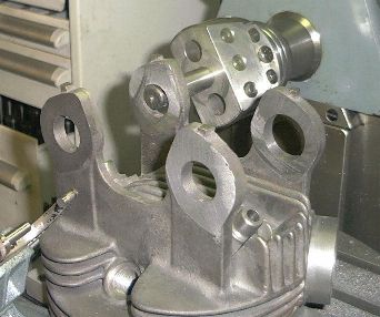
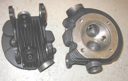
| Well, this is how it looks now. Machined combustion chamber, gasket
surface & spigot, valve seats, valve guide bores, bolt holes & threads and
exhaust port stub.
A few more hours went into making the plate in the background, which serves to hold the head 'ears up' while still knowing where the centre of the combustion chamber sphere is! |
|
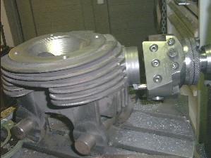
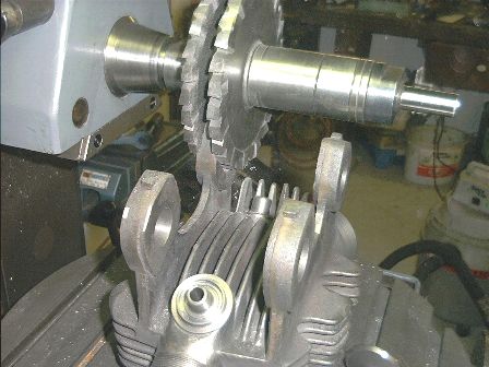
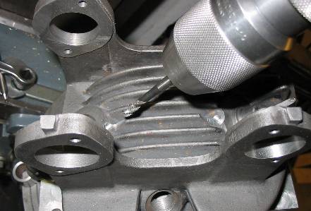
| As the tilting table does not tilt to more than 45 degrees, I had to tackle the inlet port stub this way. It looks a bit weird, but the mill did not tip over! |
|
| And again, finish the outer diameter with the Wohlhaupter. Unfortunately I cannot screw cut on the mill, I will have to think of how to make the thread later... |
|
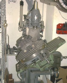
| Now, this starts to look like an engine (if you take an optimistic view...) |
|
| Now I found we still need nice level flats for the valve springs to sit on... |
|
| and a spark plug hole! |
|
| 8-11-02 after a little break, the show goes on. The inlet port threads. I made a little jig to hold the barrel. |
|
| With this, the head can go onto the lathe. I had machined a centre into the ports when the heads were on the milling machine, but one of them was not quite good, so I had to re-machine it. This looks a bit tricky... |
|
| ..but it worked out well. |
|
| Now, screw cutting was easy, although it required grinding a somewhat special tool. |
|
| When trying to fit the valve springs I found that they needed more
space.
So back on the mill, and Wohlhaupter time again... |
|
| 3/2004: I had been busy with other things, but now I got back to the
cylinder heads. They still wanted machining the "dog ears".
As the rocker supports are not too stiff in the sideward direction I decided it would be best to use a big straddle cutter for machining the sides. Unfortunately the cutters needed to be very big, so big that I could not fit the outrigger bar over them, thus the whole operation was a bit precarious... |
|
| Next step was machining the bearing seats.
This is a real precision job, as you do not want the bearings to be sloppy in the bores. |
|
| Then you still need to drill 8 holes for the bearing plates in the right
positions.
Thanks to having jigged up the head centrally on the rotary table I only had to traverse to 4 different positions, but anyhow I wished once more I had a DRO on my mill! |
|
| 6/2004: Now the heads looked nice with the valves fitted, but I
discovered that on one head the bolt threads looked a bit poor, obviously
due to (sorry MFC) poor material quality.
I decided this would not give me peace of mind, thus I fitted high tensile (42MnCr4) threaded bushes in these. These have a slightly coarser M16*1.5 thread on their outside and the original 7/16 cycle thread inside. Here I cut them back level to the face. |
|
| Next, I was worried about the lack of oil supply on the valve stems.
Thus I decided to drill oil feed bores. I will still have to make up my mind if I am going to install an automatic oiling system for the valves or just use oil nipples, but at least now I can get the oil to the spot where it is needed, i.e. into the guides! |
|
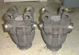
| 10/2004: Now the heads looked nice, especially on the engine, but I
decided that it would not make sense to fit the bearings etc. before they
had their finial finish.
Thus I stripped the valve gear again, took a lot of care to mask off all the machined faces (and there are quite a few of them!), sandblasted the whole lot and gave it two coats of heat-resistant paint. |
|
| To be continued.... |
Any kind of feedback to
![]() is
appreciated
is
appreciated
(sorry, this is not a clickable 'mailto:' hyperlink. If you want
to write me, please type my address in your mailer. )