 Vintage Workshop
Services for Brough Superior motorcycles and their contemporaries
|
Vintage Workshop Services for Brough Superior motorcycles and their contemporaries |
KTOR crankcase castings last update: 01-2005
First, I thought there must be some suitable castings available somewhere. So I did some research.
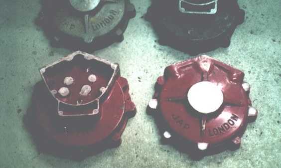
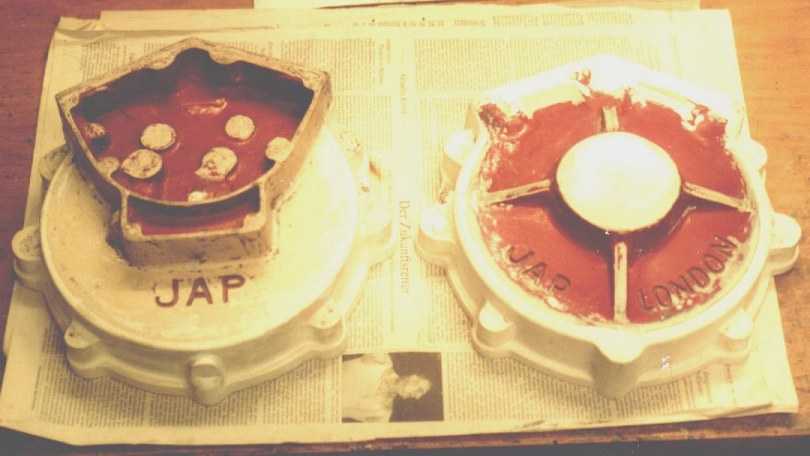
I found a number of different looking castings are available. Some have four strengthening webs on the drive side, some not, some have also three webs around the timing case. Some use a indented lettering for the JAP - LONDON logo, some have raised letters saying JAP TOTTENHAM LONDON. Then there is still a choice of timing cover versions: single or twin bevel driven mags or a chain-driven one. Some have provisions for a quill to feed oil into the crankshaft end, some not.
I found the development of the crankcases can roughly be summed up as follows:
In ca. 1922 .. 24 (side valve engines) we find a sharply V-shaped timing case (single camshaft) on a thin-walled crankcase with a nearly flat surface on the drive side and a very small bearing boss (plain bearing bushes)
The early KTOR cases ('25 & '26) have
already got the wide twin cam timing box with the oil breather box below it.
These engines do not use an oil feed quill into the crankshaft end; oil is
drawn up from the breather box into the timing side main bearing, from where a
groove in the flywheel collects it and delivers it via centrifugal force to
the big end.
On the drive side we find a bigger bearing boss on a slightly domed surface
without strengthening webs and the big JAP Logo at the top and TOTTENHAM
LONDON at the bottom in RAISED letters. No strengthening ribs on the timing
side, but a raised JAP logo under the breather box.
The late KTOR ('27 & '28) engines, and
the early JTOR ones ('28 & '29) seem to use the same crankcase. This has four
strengthening webs around the drive side bearing boss. As a consequence, there
is no space for the JAP logo at the top. Thus, these cases are labelled JAP
LONDON in the two lower quadrants of the drive side shell, still using raised
7/8" tall letters. There are still no strengthening webs on the timing side (I
am not quite sure for 1929), and still a raised JAP logo under the breather
box.
These engines do obviously use a timing case cover with an oil feed quill from
the oil pump.
From 1930 onwards, it seems JAP's noticed that the crankcase surface is much easier to polish without the protruding letters, and they used an indented lettering (in the same places) instead.
Please correct me if I am wrong!
On top of the question of general style, there is still a question of quality:
some castings are very good from an engineering point of view, but are much
thicker and wider than the originals; some look good but you find their makers
did not include any allowance for shrinkage, thus they are plainly too small to
accept a standard crankshaft. Some are obviously made from scrap aluminium and
have a myriad of pores ...
I found one manufacturer who makes a very good crankcase casting, this is the Cullingworth family at MFC castings. They can be found at http://www.japbits.co.uk . If I was to build a later Brough or a Morgan racer I would certainly use these castings. But I feel they just do not have the vintage look, and there is a lot of material that would need removing to make them look like the 1927 ones.
Sorry, what I really want is : The 1927 type, with 4 webs on the drive side, raised lettering and a timing cover for a chain driven magdyno with a direct oil feed to the crankshaft. And a Brufsup logo on the mag chain cover...
This is why I decided to go my own way.
Please have a look at what kept me busy during the last few months:
(as always, click on the pics to enlarge)
|
please click on pics to enlarge |
|
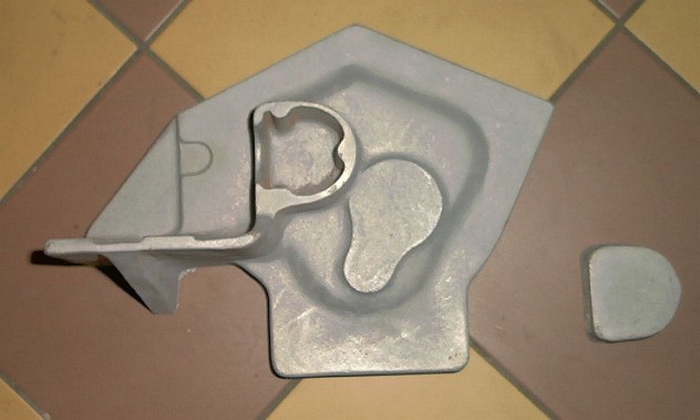
| On a visit in England, my friend Miles took me to a friend's workshop to have a look at some crankcase castings. These were of the variety "nice, but a trifle too small". As said friend must have come to the same conclusion, he offered me the patterns, would I like to modify them and cast my own crankcases. I realised that it would be a lot of work, but as he asked a very reasonable price we struck a deal. |
|
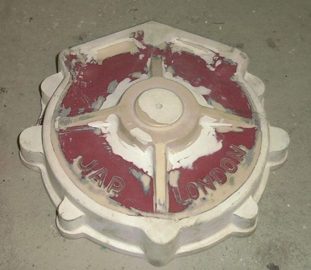
| This was the inside of those patterns |
|
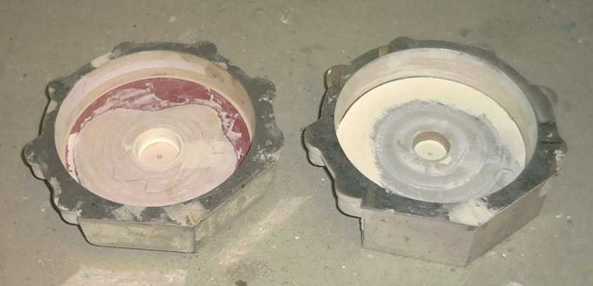
| First, I derived a pattern drawing from my crankcase
drawings. This told me that I had to add some material almost everywhere.
I started on the central joint, on which I epoxy glued a 2mm aluminium plate that had been cut to the correct size and shape. Then I added some polyester filler to the periphery, using thin glued-on plastic tubes as a guide. |
 |
| This is the result of step one. Oh I forgot to mention, in the end I had to scrape all the paint off, like with my milling machine, great fun... |
 |
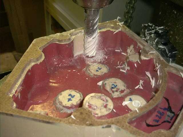
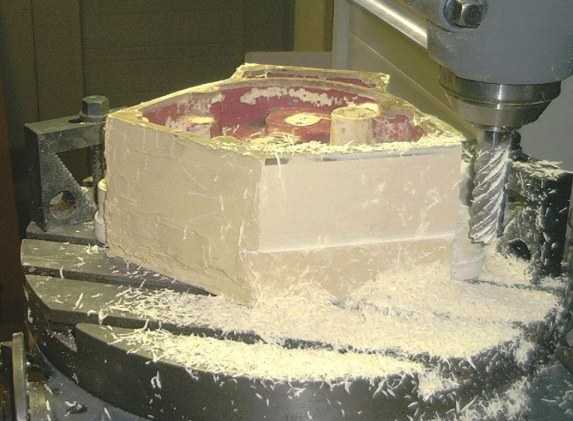
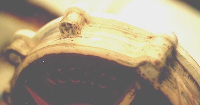
| Then I attended to the unshapely drive side bearing boss. Milling these surfaces which are inclined in 3 planes was quite some feat, but the result gave me hope! |
|
| Next step was enlarging the inner diameter, creating flat surfaces on the sides and proper dimensions in the bearing seats. |
|
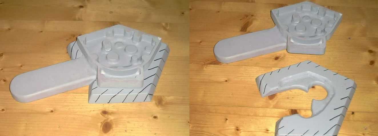
| I could fill a few pages with a description how I made the
timing case cover pattern from scratch. Basically I took an old original part, added allowances using thick cardboard and wax, made a big plaster mould of it and cast it in PU resin. The resulting shape needed cleaning up on the mill all around (and inside) in order to have flat surfaces with the correct draft. The same procedure again for the mag chain cover. |
|
| The timing case cover had been machined to the correct dimensions derived from the drawing. Of course it did not mate up with the crankcase side of the timing chest. I plotted the correct contour onto a piece of a 5mm compound plate (there was not enough depth in the timing chest and no machining allowance on the jointing surface) and glued that on. Then I added a tin of polyester filler on the outside, and made enough room in the inside, using a tapered milling cutter to give 2° draft. I also machined all along the outside, adding more filler where necessary... |
|
| I also wanted a proper machining allowance on the cylinder base flanges. And a correct 50 degree angle. And a smooth surface with the correct draft. |
|
| Well, finally I sprayed on a layer of paint, just to see all
the small defects I had not noticed before. Some more filler and emery
cloth, another layer of paint, and there we were! If had to do it again, I swear I'd rather fabricate the whole thing from scratch than starting with a too small pattern! |
|
| Oh, I forgot. You cannot mould a pattern in the sand very well when its outline does not lay flat on the ground. Thus, for some bits, you need a thing which is called 'Aufstampfboden' in German. A friendly guy out there told me this is called "follow board" in English, thank you, Shaun! |
|
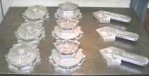
| And this, ladies and gentlemen, friends and neighbours, is
the outcome! Oh, yes, I am well aware that it is still a long way to a complete and running engine... |
|
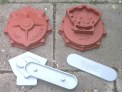
| 3/2003: I have now also made a pattern for the bevel drive timing cover. This is a casting made from it. |
|
| A word for clarification: I have made these castings to build my own engine. I am not in it for a business, so please don't ask me for these castings - they are not for sale I am afraid. |
Any kind of feedback to
![]() is
appreciated
is
appreciated
(sorry, this is not a clickable 'mailto:' hyperlink. If you want
to write me, please type my address in your mailer. )