 Vintage Workshop
Services for Brough Superior motorcycles and their contemporaries
|
Vintage Workshop Services for Brough Superior motorcycles and their contemporaries |
V-twin crankshaft balancing last update: 8/2008
Well, if I make a crankshaft I will have to balance it. And if I machine the flywheels from solid it will be as well to think of my balancing before I make the flywheels. If I CNC machined them and I knew what I was doing, I could design them to need no further balancing at all.
IF I KNEW WHAT BALANCE FACTOR I WANTED, THAT IS!
Do YOU know? To be honest I don't!
So this is what this page is about. I will tell you what I know, and I kindly ask you: If you know any more than I do, please help me!
In the meantime a discussion of this topic has been
initiated on a German forum. For the benefit of those who are having
difficulties with English I have now mirrored
this page in German.
Also, in the course of this discussion, I have found a few smaller mistakes in
the graphical representations given below, which I have now corrected as well.
If you are a serious engine builder, please do me a favour and read on - you might learn something you did not know, and if I am lucky, you might be able to help me out. So here I go...
|
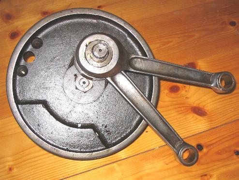
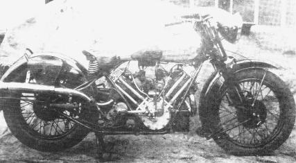
It seems to be commonly accepted that something between 50% and 57% is a good balance factor for a single cylinder engine, depending on the conrod length and other factors. But what is a good value for a 50° V-Twin? I have asked a lot of people, but so far, I was only quoted two rather different numbers, telling me to use a balance factor of 65% or 35%, respectively. Unless these are based on a different definition, at least one of them must be wrong. Unfortunately I have never measured the balance factors on the bikes I am riding. However, I have made some measurements on two other JAP V-twin cranks recently. On a 680 ohv JAP engine I found a balance factor of about 43%. On a ca. 1925 KTO crankshaft a fellow Bough Club member thankfully lent me (see picture) I found a balance factor between 42% and 38%, depending on the weight of the pistons (which do no longer exist) I assumed between 460 and 540 grams. This seems to tell me JAP's used a balance factor of 42%. The value of 65% looks rather improbable from this. Maybe some of the above figures are based on different definitions? |
|
|
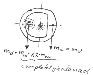
My understanding of a balance factor is the following: The mass of the connecting rod and piston are divided into a rotating and a reciprocating part. The rotating mass mrot consists of the big end bearing and the weight of the lower rod ends measured by resting their lower ends on a scale while supporting the small end in the centre of the bore so that the rod is horizontal. The reciprocating mass mrec is the weight of the complete piston assembly including rings, gudgeon pin etc. plus the weight of the upper rod end, determined by reversing the above method. Now, in order to obtain a balance factor of X%, you balance the crank for 100% of the rotating mass mrot plus X% of the reciprocating mass mrec To achieve this, you make up a dummy weight to go on the crankpin which has a mass md = mrot + X%*mrec. Then you modify the counterweight mass mc on the flywheels so that the shaft is in perfect balance. If we are dealing with a V-twin engine, the masses mrot and mrec need to include BOTH pistons and BOTH rods to make a sensible definition – do you agree?
|
|
| So far so good. As none of the above figures seemed very convincing, I
went for a theoretical analysis of the problem: I derived
the equations of motion for an engine consisting of the above mass elements.
The picture to the right hand side just shows the basic equation for the piston travel yp vs. crank angle phi. If you click on it, you can download the whole sheet with the first and second derivations, giving the piston speed and acceleration. (Sorry for my messy handwriting, when I find the time I'll try to write this up a little more nicely!) |
|
|
Then I made a spreadsheet to calculate and plot the horizontal and vertical force components Fx and Fy occurring during one engine revolution as a function of the crank angle. I have toyed a little with this spreadsheet, looking at a number of basic test cases for a single cylinder engine to check whether it yields sensible results. I think it did, but let's have a look at them. They will give a nice step-by-step introduction to the problem. Test case 1: no balance at all. With
a balance factor of 0% we only balance the rotating parts. The engine
(assumed to stand upright) thus creates some unpleasant vertical forces, due
to the unbalanced mass forced of the piston travelling up and down. However, this is just giving the magnitude of the force, but it tells nothing about the direction. I have thus added a polar plot on the extreme right hand side. This shows the total force and its directions: you can see that it is just going up and down in this case. |
Test case 1:
|
|
Now please look at test case 2, which is all the same, except for the balance factor: I have changed this to 100% now. As we might expect, all the vertical forces have disappeared now, as the reciprocating weights are 100% balanced, but we create a corresponding unbalance in the horizontal (fore and aft) direction, because there is no force to counteract the centrifugal force of the bob weight when it swings to the front or rear of the engine.
|
  |
|
So, the best thing we can do is find a compromise, trying to keep the total of these forces as low as possible. For an engine with an infinitely long conrod, this would mean a balance factor of 50%. This is test case 3, and you can see results in the adjacent graphs. The horizontal and vertical forces now have the same amplitude, but a phase shift of 90°. Their vector sum combines to a total force of some 1600N, which is uniformly rotating around the crankshaft centre.
However, a real engine does not have an infinitely long connecting rod. Normal conrods lengths are about 2 or 3 times the stroke of the engine. The limited rod length means that the piston does not follow exactly the elevation of the crankpin, due to the conrod being out of vertical for most of the time. E.g. at 90° crank angle, the piston is significantly below mid-stroke, due to the inclination of the conrod. This adds a sine square function to the cosine function representing the piston travel vs. time (or vs. crank angle), thus adding a component varying with twice the engine speed. The effect of this can be seen on the two adjacent graphs, representing the case of a 7.75" long conrod, and still 50% balance. The total unbalance force is no longer constant, and its maximum has now risen from 1600N to about 2200N. |
    |
|
If we try to minimise this peak value of the unbalance force, we will come to a balance factor of 58%, see adjacent graphs. This seems to be the optimum value for this rod length. Now you could argue if the height of these peaks (occurring at 0, 100 and 260 degrees of crankpin angle) is the most important criterion for best balance, or if we should look at the mean out-of-balance force averaged over one engine revolution. I have thus toyed with a range of balance factors and have tracked the resulting forces. The second plot is giving the peak force, the mean force and the amplitudes of the horizontal and vertical force as a function of the balance factor. From this it can be seen that the peak force is lowest at a balance factor of 58% and the mean force is lowest at 54% balance. I agree you cannot really see the latter from the plot, but it can be seen in the figures it is based on. However, what you can see is that the mean unbalance force is not changing much at all when we change the balance factor. It is almost constant in the range from 45% to 65% of balance. Thus I cannot see a good reason to go for 54% of balance, giving much higher peak forces.. I think the conclusion is that 58% is the best balance factor for a single cylinder engine with a rod length-to-stroke ratio of 2.32 (7.75"/85mm). |
   |
| Now, what happens in a 50° V-twin engine? We just need to model the second rod and piston, and have both pistons travelling on two axis' (axisses?) inclined by -25° and +25° to the vertical axis. At 0% balance and infinite rod length, we find the maximum force at some 5200N,compared to 3200N in the single cylinder case. For a parallel twin we should find it doubled, but we have a 50° cylinder angle here. As the piston movement is split into a horizontal and a vertical component, there is a horizontal force component here, and the vertical component is accordingly reduced. In accordance with the single cylinder findings, things are just changed, but not improved, if we go to 100% balance, see second picture.
|
    |
| In the real 50° case, with the KTO engine's relative rod length of
2.32, the lowest peak force is obtained at a balance of 53%, see adjacent
graphs.
By the way, isn't the 50° engine doing quite well, with the maximum out of balance force being only about 1.4 times the ones of a single cylinder engine having the same bore and stroke?
Again, if we compare the two criteria lowest peak force and lowest mean force, we cannot find a reason not to go for 53% of balance. So, after all of this, my question is: Does any of you experienced engine builders out there see a reason to
use any balance factor other than 53% for a KTO JAP engine? |
   |
|
As a post-up, please allow me a little digression, and have a look at the adjacent graphs: It shows the unbalance forces for a 90° V-twin engine balanced to 50%: THERE AREN'T ANY!
Ok, this is the theoretical case of infinite rod length, but even if we use the above 7.75" rod, things are still looking quite nice, see second picture. There are these often criticised high-pitched horizontal excitation forces, but just look at the level, a mere 1000 N! Maybe it is time to switch to a Moto Guzzi?
|
    |
| Should I ever get bored after building my replica SS100, I'll try to recreate that one! |
 |
Any kind of feedback to
![]() is
appreciated
is
appreciated
(sorry, this is not a clickable 'mailto:' hyperlink. If you want
to write me, please type my address in your mailer. )